netTerrain 9.6 Integration Toolkit Guide

Document Code. GN_D_nT9-04 Last revision: 03/24/2023
© 2023 Graphical Networks LLC. All rights reserved (but some wrongs are still available).
Our “keep the lawyers happy” disclaimer: Graphical Networks and netTerrain are registered trademarks of Graphical Networks LLC. Other product names mentioned in this manual may be trademarks or registered trademarks of their respective companies and are hereby acknowledged.
This document was created with 100% recycled electrons.
Before printing, please be mindful of that PC load letter and consider the environment when hitting the printer with a baseball bat.
Image: Azores, Portugal.
Graphical Networks LLC
Telephone: +1-240-912-6223
Fax: +1-240-912-6339 (where you can send us the purchase orders)
1 About this guide
1.1 Who should use it
The Integration Toolkit (ITK) is an application for importing data from third-party systems or home-grown databases and files into netTerrain. It also has a built-in discovery engine supporting several protocols such as Simple Network Management Protocol (SNMP) and Windows Management Instrumentation (WMI).
The ITK is part of the netTerrain application installer, and it is deployed on the netTerrain application server. Upon request, Graphical Networks can also provide a separate installer for the ITK, which can be deployed on individual computers. In those cases, a database connection from the computer to the netTerrain database will be required.
This guide is intended advanced users that want to automate the data entry into netTerrain by setting up discovery processes or creating and managing connectors to external systems. In short, geeks like us.
1.2 Assumptions
This guide assumes basic knowledge of database queries, Microsoft Office tools and netTerrain end-user and power-user functions.
Discovery functions may require the user to have knowledge about WMI, SNMP and the Management Information Base (MIB) structure.
2 Integration Toolkit basics
The Integration Toolkit (or ITK) is an application that provides users with the ability to import and synchronize data into netTerrain from external databases or files, as well as auto-discovery functions. The ITK is a .NET based fat-client application that runs on the netTerrain application server. As mentioned above, upon request, Graphical Networks can also provide a separate installer for the ITK, which can be deployed on individual computers. In those cases, a database connection from the computer to the netTerrain database will be required.
The toolkit includes several methods for pulling data from the network:
- Built-in device connectors: predefined connectors that read device data from external data sources
- Custom device connectors: user defined connectors that read device data from external data sources
- Node connectors: user defined connectors that read generic node data from external data sources
- Link connectors: user defined connectors that read link data from external data sources
- An SNMP discovery engine
- A WMI engine
- An AWS connector
- IPMI and other protocols using Intel’s DCM API (separate module required)
- A SQL Server database discovery utility
The first four methods (connectors) support native database connections to SQL Server, Oracle, PostgreSQL, MySQL and Microsoft Access. If the data is stored in a different database engine or file format, you can implement a “proxy database” to gain access to those data sources and still import the data into netTerrain.
All connectors support the three basic database operations for inserting, updating and deleting records (the infamous CRUD operations). What this means is that nodes and links can be automatically created in netTerrain, based on new records coming from the original data source and existing nodes and links in netTerrain can be updated or deleted, if the records experienced a change or were removed from the source database.
The SNMP discovery tool supports SNMPv1 and SNMPv2c for discovering devices, ports, IP address tables and layer 2 and layer 3 links (by means of bridging and routing tables) from the network and SNMPv3 for device discovery.
The WMI discovery tool can discover hardware and software characteristics from WMI enabled devices, as well as application and IIS data.
The ITK also ships with a predefined connector for discovering data from AWS instances. This connector uses the AWS API and can import regions, groups, rules, instances, volumes, health checks and buckets, among other things.
With the adequate license, the ITK can also include the Intel DCM module that can monitor power and temperature variables from select devices. This module is outside the scope of this manual.
The SQL Server monitor uses an ADO.NET native SQL connection to read database and instance information from registered SQL database engines.
2.1 Main user interface components
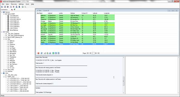
The ITK is a thick client application with a User Interface (UI) that simplifies the process of creating and maintaining connectors, as well as importing data into netTerrain. The main ITK UI components are accessed from a switchboard, as shown in the image below.
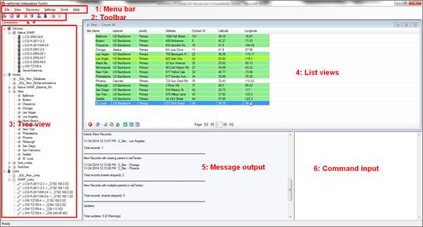
ITK switchboard and UI
The Menu bar (1) provides easy access to common functions for managing the ITK (File), viewing objects (View), discovering records from external systems (Discover), managing the application, connector and auto discovery settings (Settings), creating new connectors and administering the log files (Tools) as well as accessing the guide and software version (Help).
The toolbar (2) includes a few shortcuts to common functions for accessing the connector lists, creating new connectors and starting and stopping the automatic discovery with the scheduler.
The tree view (3) shows all connectors and their discovered objects.
The list views (4) can display all device, node and link connectors set up in the system, their discovered objects, as well as other lists such as mapped types.
List view showing the filter text box
The message output (5) provides the user with the status of finished or ongoing discovery and reconciliation processes as well as output messages from commands issued from the command input window (6).
Attention!
The command input window is mainly used for development and consulting purposes, but several commands (see chapter 7) are available to end users.
2.2 Nodes vs devices
Throughout this guide we will be working a lot with device and node connectors, which are responsible for automatically creating and reconciling nodes and devices in netTerrain. It is important then, to know the difference between nodes and devices before choosing which type of connector to work with.
A node is a very unassuming yet flexible object in netTerrain: it can represent anything from a building to transportation equipment, a data center object, location or even a chair or person. Nodes can, of course, be connected with each other or to a device. Yet nodes are rather modest compared to their cousins, the smart devices. Nodes, as opposed to devices are not aware of sub components they may contain, their physical dimensions, let alone more sophisticated properties like weight or power usage.
If you are a user of netTerrain DCIM you probably want to use device connectors in case you need to import entities like routers or switches via the ITK. That way, you can take advantage of some of the business rules and automation that netTerrain offers. These business rules and features include:
- An extensive predefined library of makes and models
- Automatic creation of subcomponents (ports and slot)
- Automatic creation of a background image
- Awareness of physical size and weight
- Easy “snap in” for rack mounting
- Awareness of power consumption
- Ability to receive automatic alarms from the ITK
- More comprehensive modeling capabilities such as the ability to specify reference node location
- Ability to restrict which card types can be positioned under which slot
- Pre-defined reports in the dashboard
Generic nodes (or simply nodes) have none of these capabilities. They are basically just modeled as objects that have an image, a set of fields, and visual overrides.
2.2.1 Can I use node connectors in the ITK to represent devices in netTerrain?
You certainly can, but those device representations in netTerrain are generic nodes that only look like devices, but lack most of the smart business rules described above.
To make it clear: none of the features that come with smart devices prevents a user from utilizing generic nodes to represent actual devices. In those cases, netTerrain really doesn’t see a difference between your “nodes as devices” and any other node. You can certainly create a node type that looks like a router and later connect it to another instance of a generic node type that looks like a switch. The caveat is that netTerrain will treat these objects as any other generic node.
When using nodes as devices you can still overcome the lack of automatic business rules by documenting things a bit more manually. For example, if you want to document the ports of a router or switch using generic nodes, you will need to create those ports manually, and if you want to rack mount the node, you will have to resize it and fit it inside a rack diagram manually.
2.3 Device connectors
Device connectors are hooks into external databases or files designed to specifically import and reconcile device data into netTerrain. These external databases are usually back-end data stores of a Commercial-Off-The-Shelf (COTS) product. Some examples of COTS products are described in the bulleted list below.
Records that are imported from the external system using a device connector will be mapped to smart devices in netTerrain. A type field must be used to associate each device type with its corresponding type in netTerrain without having to create a specific connector for each device make and model.
Besides the built-in device connectors that already ship with the netTerrain software, a wizard allows you to create their own device connectors, enabling real-time or near real-time import and reconciliation of device data into netTerrain.
Graphical Networks has created several device connectors to external systems for different customers in the past, including:
- Solarwinds Orion Network Performance Monitor (NPM)
- VMWare VCenter / Virtual Center
- Ipswitch What’s Up Gold
- Castle Rock SNMPc
- Cisco RME
- CA Unicenter Tng
- CA Concord eHealth
- Microsoft MOM and SCOM
- HP Open View Operations
- CA Spectrum
- Red Hat Linux Network
- Zenoss
Many of these predefined device connectors are made available as part of an ITK build or through XML drop-ins (explained later in this guide).
Attention!
Built-in device connectors usually bring in basic data fields. If a more in-depth integration between the third-party system or COTS product and netTerrain is needed, then it may be more convenient to create a custom device connector from scratch using the ITK wizard. If your organization has an active maintenance license you can request Graphical Networks to create the connector free of charge, provided it is to a COTS product.
2.4 Node and link connectors
Node or link connectors are hooks into external databases or files to pull in records and map them to new or existing generic nodes and links in netTerrain.
Users can create any number of node and link connectors and each one will be mapped to a predefined type in the netTerrain catalog. To create a connector, a wizard to connect to the data source and map source fields to custom fields in netTerrain is available.
Attention!
For netTerrain DCIM or netTerrain Enterprise users we recommend using device connectors to bring in device data into netTerrain. That way you can take advantage of the built-in intelligence associated with smart devices (such as automatic port creation).
2.5 Monitoring
The netTerrain ITK currently supports various monitoring mechanisms: an SNMP discovery engine, WMI, Website monitoring (static sites and WMI-based IIS discovery), a built-in IPMI environmental monitoring engine (for licensed users that purchased a license of netTerrain with the Environmental Monitoring module, such as netTerrain DCIM-EM) and a SQL Server monitoring utility.
The SNMP discovery module provides a simple way to discover devices within one or more IP address ranges using SNMPv1, SNMPv2c and SNMPv3. Using SNMPv1 and SNMPv2c the ITK can discover device data, interface data, IP address tables and layer 2 and layer 3 links (by means of bridging and routing tables). With SNMPv3 the ITK currently only supports device discovery.
The WMI discovery tool can discover hardware and software characteristics from WMI enabled devices, as well as application and IIS data.
The netTerrain Environmental Monitoring module can provide environmental data such as power and temperature variables from select devices using the IPMI protocol.
The SQL Server monitor can discover SQL Server instance statistics, as well as statistics for each database that resides in one of the monitored instances.
2.6 Architecture
The following diagram represents the system architecture, along with the components of the ITK.
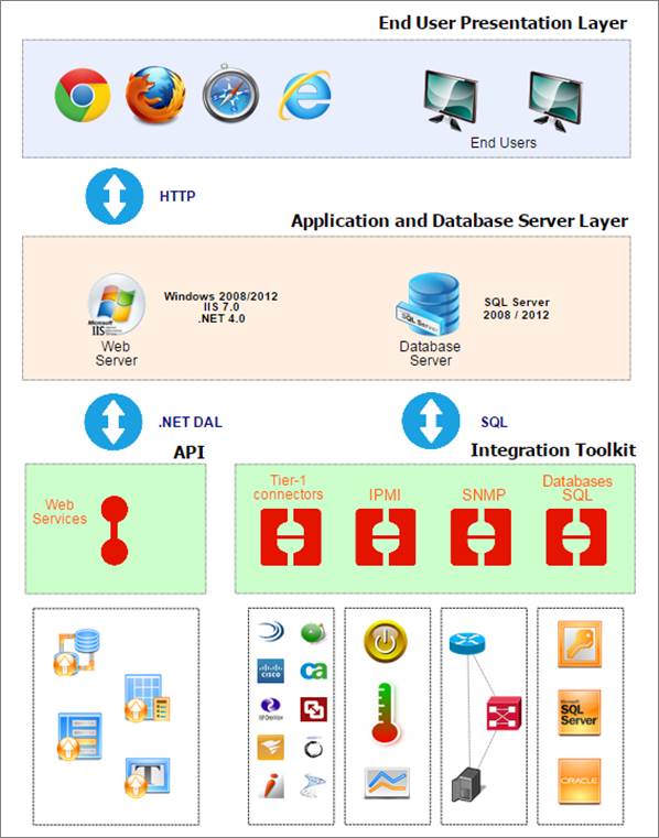
netTerrain and ITK architecture
The ITK components are represented on the bottom right corner.
2.7 Setting up the ITK for first time use
The ITK is installed on the application server and launched from the Program Files->netTerrain shortcut folder.
When launching the ITK for the first time the connection to the netTerrain database may fail since the connection string stored in the ITK xml file has the default (factory shipped) credentials.
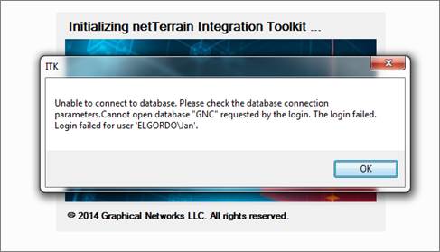
Failed connection dialog
By clicking ‘OK’ the system will prompt the user to enter the credentials to the netTerrain database:

Dialog to enter the netTerrain database credentials
The ITK needs a valid user set up in the netTerrain SQL Server. This user can log in via SQL Server or Windows authentication and it requires a permission level enough to modify table structures in the netTerrain database (such as db_owner or a combination of db_datareader, db_writer and db_ddladmin).
A connection timeout parameter can also be set. Usually 30 or 60 seconds is sufficient for normal ITK operations. However, because this parameter not only controls the timeout between the ITK and the netTerrain database but also the timeout between the ITK and source database engines, if you suspect that certain connectors may have long processing times during data querying you may want to increase that timeout value.
After testing for a proper connection, click on ‘Submit’ and the application will try to connect again. If the connection has been correctly set, you should see the ITK Main switchboard.
Main switchboard
If you still get an error after trying to relaunch the ITK, then the connection parameters are wrong. You may need to consult with your netTerrain DBA what the proper connection parameters are.
2.8 Setting up the ITK as a service
The ITK can run as a service on the machine it is installed on. This has the following advantages:
1) The service account can start the ITK
2) If the machine is restarted, then the ITK will launch automatically
Also, it is worth noting that if the ITK had a scheduler running and the server restarts, upon restart, the scheduler will be active and the timer will resume where it left off.
2.8.1 Installing and starting the ITK service
To install the ITK as a service you need to follow these steps:
1) Open a command prompt with elevated permissions
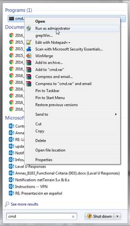
2) Execute the following command: "C:\Windows\Microsoft.NET\Framework\v4.0.30319\InstallUtil.exe" "C:\ProgramData\Graphical Networks\netTerrain\ITK\netTerrainITKService.exe"
a. Note that the first folder may vary for different versions of windows, so consult with your system admin as to where the install utility for the .NET framework is installed.
b. The second folder is the installer folder for the ITK, which also may vary depending on your netTerrain installation.
3) Go to the services utility, and start the ITK service
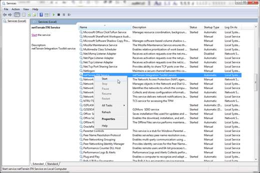
The ITK is now installed as a service and activated. To stop the service simply use the services utility as shown above.
2.8.2 Uninstalling the ITK service
To uninstall the ITK service you need to follow these steps:
1) Open a command prompt with elevated permissions
2) Execute the following command: "C:\Windows\Microsoft.NET\Framework\v4.0.30319\InstallUtil.exe" /u "C:\ProgramData\Graphical Networks\netTerrain\ITK\netTerrainITKService.exe"
2.9 Obtaining the ITK version
In case of problems, if you contact Graphical Networks support we may request the ITK version number. This can be obtained from the Help->About menu.
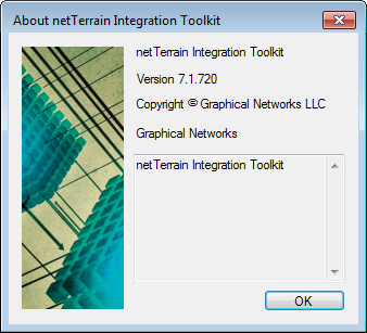
About dialog
3 Built-in device connectors
netTerrain has a UI to create new device connectors for any third-party data source that uses an Oracle, PostgreSQL, MySQL, SQL Server or MS Access backend database. netTerrain also includes a series of built-in device connectors that require basic connection and reconciliation parameters to perform automated imports. These device connectors are sometimes referred to as built-in (or tier-1) connectors, as they were created in advance by a Graphical Networks engineer and are already available in the ITK, either as part of the factory installation or as a drop-in XML file.
3.1 Viewing available connectors
To see which device connectors are currently included in your ITK configuration, go to the View-> Device connector list (Ctrl-A) and a list view of all the tier-1 device connectors will show up.
Device connector list view
Your initial ITK deployment may not have any tier-1 device connectors available, in which case netTerrain provides a feature to “drop” new tier-1 device connectors into the database, which is reviewed later.
The current list of drop-ins includes the following device connectors:
- CA Unicenter
- Castlerock SNMPc
- Cisco RME
- Concord eHealth
- Microsoft MOM
- Microsoft SCOM
- Solarwinds NPM
- Whats Up Gold
You can request additional drop-ins from Graphical Networks by logging a drop-in ticket request in the customer support portal.
3.2 Deleting connectors
You can easily delete a connector by selecting it from the connector list and clicking on the ‘Delete’ button (or right clicking on the connector and hitting delete).
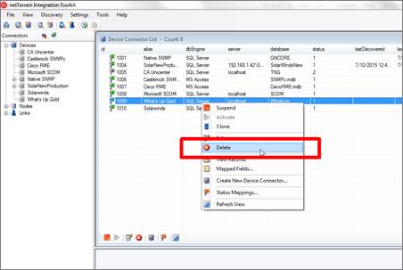
Deleting a connector
Attention!
Once a device connector is deleted you can only bring it back by creating it manually, using a drop-in or restoring the netTerrain database. It may be better to not delete the connector and simply mark it as suspended if you think you may use it later.
Also note that when you delete a device connector, any type mappings (more on that later) associated with that connector will also be deleted!
3.3 Setting up a built-in connector
When importing data from a third-party system that is included in the tier-1 connector list, you typically just need to set up the backend connectivity and specify a series of basic parameters for proper data reconciliation.
3.3.1 Using device connector “drop-ins”
Your initial ITK deployment may not have any tier-1 device connectors available, in which case netTerrain provides a feature to “drop” new tier-1 device connectors into the database. This feature can also be used for creating new device connectors or even cloning existing ones.
Drop-ins are XML files that can be imported into the ITK via the drop-in import menu option. netTerrain already ships with several XML files (essentially the tier-1 device connectors displayed on our website). These XML files include a section that specifies the connectivity and main mapping and another section that includes all the extra fields that will be mapped into netTerrain. Below is an example of the Solarwinds drop in:
<?xml version="1.0" encoding="utf-8"?>

<Main>
 <Connector>
  <ConnectorName>Solarwinds</ConnectorName>
  <DatabaseEngine>SQL Server</DatabaseEngine>
  <DatabaseServer>localhost</DatabaseServer>
  <DatabaseName>NetPerfMon</DatabaseName>
  <Table>Nodes</Table>
  <NameField>Caption</NameField>
  <DeviceType>sysObjectId</DeviceType>
  <ParentNetworkField>Location</ParentNetworkField>
  <Icon>Orion.ico</Icon>
 </Connector>
 <Fields>
  <Field1>
     <Source>DNS</Source>
     <nT>Dns</nT>
  </Field1>
  <Field2>
     <Source>IP_Address</Source>
     <nT>Ip Address</nT>
  </Field2>
  <Field3>
     <Source>Status</Source>
     <nT>Status</nT>
  </Field3>
  <Field4>
     <Source>SysName</Source>
     <nT>sysName</nT>
  </Field4>
  <Field5>
     <Source>SystemUpTime</Source>
     <nT>sysUpTime</nT>
  </Field5>
  <Field6>
     <Source>Description</Source>
     <nT>sysDescr</nT>
  </Field6>
  <Field7>
     <Source>Contact</Source>
     <nT>sysContact</nT>
  </Field7>
 </Fields>
</Main>
The screenshot below shows how to import a drop-in into netTerrain.
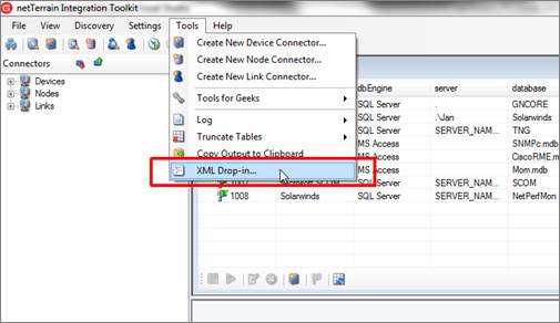
Device connector drop-in feature
Once you click on the XML Drop-in menu option a new dialog prompts the user to browse for the drop in XML files. The default directory is the DropIn folder in the ITK installer folder, which already includes several predefined XML drop-in files. After selecting the drop-in and clicking OK, you will be asked a few basic questions about how to connect to the data source. The ITK will then restart and the new device connector should be registered in the tool.
Attention!
XML drop-in files only include basic field mapping information. For a deeper integration you may need to add more mapped fields or switch from a raw source table to a custom view.
Tip:
Use your GN maintenance! We can deliver a new XML drop-in for you or simply help you in creating a connection to any COTS product at no charge. This is another good reason to be current on your netTerrain maintenance!
3.3.2 Setting up the connection to the data source
Device connectors can communicate with any third-party tools that store the data in an accessible Oracle, PostgreSQL, MySQL, SQL Server or MS Access repository. If the third-party tool uses a different repository, the device connector can still be created by setting up an intermediate SQL Server or MS Access repository that establishes an ODBC connection to the source. This intermediate database is sometimes referred to as a ‘proxy database’. We discuss proxy databases later in the guide.
Since built-in connectors include a lot of predefined data, setting them up in your environment essentially consists of just editing some basic parameters in the connector settings dialog.
Go to the Settings tab and hover over ‘Device Connectors’ and click on the particular device connector that needs to be set up.
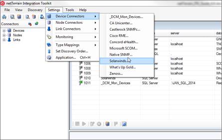
Device connector settings menu
The settings dialog includes a series of input fields to set up connectivity parameters, such as database credentials, mapping parameters and reconciliation rules.
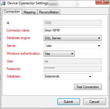
Device connector settings
The connection tab includes fields to specify the database server, database name and credentials for connecting to the third-party system. Note that certain fields may be enabled or disabled depending on the database engine that is chosen. For example, server, user and password do not apply for an MS Access database.
3.3.2.1 Source Database
If the database engine is SQL Server, then the database field does provide a drop-down box of all the databases available on that engine. For MS Access-based connectors use the ellipsis ‘..’ button to browse for the file (.accdb and .mdb extensions are supported). For Oracle-based connectors you must type in the TNS reference. For PostgreSQL-based connectors the Server field turns into a ‘DSN’ field. You must then make sure there is a DSN to the PostgreSQL database (from the machine hosting the ITK) and then reference that DSN in the DSN field.
3.3.2.2 Testing the connectivity
To test the connectivity after filling out the proper credentials, you can click on the ‘Test connection’ button.
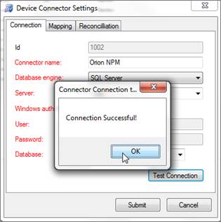
Testing for database connection
3.3.3 Mappings tab
The mapping tab includes several important fields that need to be properly filled out for the connector to discover data from the data source correctly.
Attention!
It is important to understand the structure of the data source you want to import data from. For example, you need to know what table or view contains the devices to be imported as well as which fields contain the unique naming convention and device type information.
Also, if you change any fields in the mapping tab currently associated with an additional mapped field (see additional mapped fields section), then the mapped field will be removed from the mapped field list.
3.3.3.1 Source table
The source table represents the table or view where the records that need to be pulled from the data source are stored.
Tip:
If you need to modify some of the data being imported into netTerrain or need to correlate more information that is available in other tables, create a view that “massages” that data for you and point the source table field to that view.
3.3.3.2 Device type field
The device type field is the data field in the source table that holds the identifier for the type of device that will be mapped with the corresponding type in netTerrain. netTerrain uses a name field in the node catalog table to identify a device type. In other words, netTerrain will try to map the type name from the source with the node type library name in netTerrain.
Tip:
The most accurate descriptor of a device type is the system object id (usually called sysObjectId or sysOID). This is the SNMP discovered unique make and model identifier for a device and can be nicely mapped to netTerrain’s existing table of OID to device type information (more on that later)!
3.3.3.3 Default diagram
When importing devices from a third-party data source, netTerrain can assign a default diagram for the device. This is especially important when the source table has no fields that can provide information about the parent diagram containing each device. This default diagram in netTerrain will serve as the initial repository for newly imported devices. You can assign different diagrams for different device connectors instead of searching for devices from multiple device connectors in one generic diagram. To specify a default diagram, at least one diagram needs to exist in netTerrain beforehand.
3.3.3.4 Parent locator field
An alternative to using a default diagram is to automatically place devices under a specific parent object. This is possible if the source table contains a field that stores that parent ancestry data. This can be specified in the parent locator field.
Attention!
For the automatic placement to work, the parent diagrams must exist in netTerrain prior to importing the devices. We recommend creating a separate connector that pulls the parent objects in advance, which will then guarantee that the devices will be placed under the corresponding parent objects. This is yet another way to further automate your network documentation process.
3.3.3.5 Name field
The name field should contain the name or unique identifier for each device, and it will be mapped to the name field in netTerrain. Technically, it is not necessary for this field to pull values that are unique, but it is highly recommended. If the name field is mapped to a field in the source table that does contain repeated values, then any devices with the same name field value will throw an error during the update process. Also, if devices do not have unique names in netTerrain, then if later on you decide to also import links using the ITK, any links that have any repeated devices as endpoints will not be imported.
3.3.3.6 Rack position field
Rack coordinates can be used to automatically place devices on a given rack and rack unit. In other words, this field can be used to import rack positioning information from the source data and avoid placing a device on a rack manually. Naturally, this requires the source data to contain the proper rack unit information for the imported devices. This field assumes that the parent for each device is a rack and is specified in the parent locator field. To summarize, the rack positioning in the ITK must comply with the following:
- The parent object type must be a rack and must exist.
- The source table must contain a field for the rack unit.
- The rack unit for each record in the source data must be consistent with the size and rack unit availability for the corresponding parent rack.
If no coordinate information is available, use the
3.3.3.7 WHERE clause
The last field of the second tab contains a WHERE clause. This can be used as a mechanism to filter certain records from the source table. The syntax of the WHERE clause must correspond to the flavor of SQL that the source database uses and must start with the ‘WHERE’ keyword (see the screenshot for an example).
Attention!
If the syntax in a WHERE field is incorrect, the discovery process will fail. When writing the clause, you must start the filter with the ‘WHERE’ keyword itself (for example ‘WHERE location=1’). Also, mind that SQL syntax as it may differ from different database engines. SQL Server uses T-SQL, Oracle uses PL/SQL and MySQL, PostgreSQL and MS Access also have slightly different flavors of SQL so there may be minor differences in the syntax. If you want to avoid all this hassle don’t use the WHERE clause and instead connect to a custom view where the information is already pre-filtered.
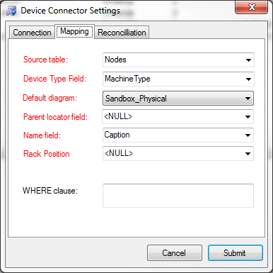
Mappings tab settings
3.3.4 Reconciliation settings
The last tab deals with the mechanism for device reconciliation into netTerrain.
3.3.4.1 Updates
If you want to update any field changes for devices that already exist in netTerrain, then set the ‘update existing devices’ combo box to ‘Yes’.
3.3.4.2 Inserts
New devices that do not exist in netTerrain and were discovered by the device connector will be inserted into netTerrain, if the following criteria apply:
- The ‘Use generic devices for unmatched types’ application setting is checked or the device type can be mapped to a type in netTerrain (see type mapping later in this chapter)
- A default diagram has been assigned for the device connector (defined in the mappings tab) or a parent container field exists, and the proper parent object also exists in netTerrain
- The ‘Insert new devices’ combo box is set to ‘Yes’
3.3.4.3 Deletes
Devices that exist in netTerrain but no longer exist in the source can be processed in two different ways:
- They can be deleted from netTerrain by setting the ‘Delete devices without matches’ combo box to ‘Yes’
- The can be kept in netTerrain by setting the combo box to ‘No’
Attention!
When the ‘Delete devices without matches’ combo box is set to ‘Yes’ only devices that were originally inserted by that same connector will be deleted from netTerrain. For instance, a router called ‘123’ that no longer exists in the data source but still exists in netTerrain, will only be deleted if it was originally inserted by that same connector. Internally, any devices that are inserted in netTerrain by the ITK are tagged with the connector id. Then, when a delete process occurs, only devices with that connector id will be deleted (provided they no longer exist in the source).
3.3.4.4 Preventing deletes for low record counts
Notice a field underneath the delete drop down box that includes a counter. This counter can be used to restrict a delete operation to cases where the number of discovered elements is greater than a certain number. Set that counter to any integer between 0 and 10 million.
The default value for this counter is always 0, in which case the delete reconciliation process (when the combo box is set to yes) will always occur.
Tip!
Use the delete counter when the data being discovered goes through a process that may not always be robust and could yield an empty table. In those situations, if the delete combo box was set to yes, you can prevent all records that were imported from that connector from being deleted in netTerrain by setting the counter to a number greater than 0.
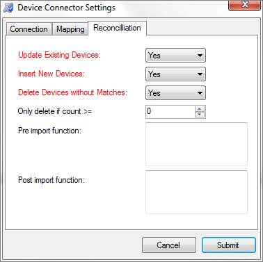
Reconciliation tab
3.3.4.5 Pre and post import functions
These fields are used to place advanced functions that are processed before and after an import occurs. An example of a pre-import function could be a call to execute a stored procedure in the source data, which massages the records to be imported. An example of a post import function could be a layout algorithm that is triggered after the import to automate node positioning.
Attention!
The Pre and Post import function fields are currently reserved for Graphical Networks consultants. If you think you need a function to perform a specific action, please enter a ticket in the support portal.
3.4 Additional mapped fields
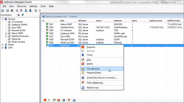
In addition to the main fields that comprise the device connector settings, extra fields can be mapped to the connector (such as the IP address, DNS name, location and so on). To find out which fields have been mapped for a built-in connector, go to the device connector list, right click on the connector and click on ‘Mapped Fields’.
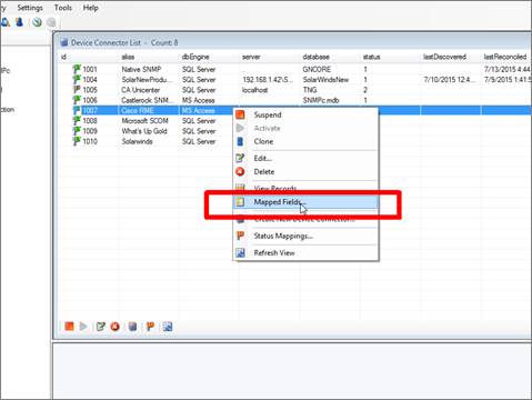
Accessing additional mapped fields
A new ‘Mapped fields’ dialog will pop up, which will show any mapped fields in the list view and provide a mechanism to remove any mapped fields or add new ones.
Attention!
If your connector doesn’t have valid credentials to connect to the source (i.e. a connection failure) then you will not be able to see the mapped fields. You can always check if your connection is valid by first opening the connector settings in edit mode. Use the test connection button to see if you have a valid connection to the source database.
3.4.1 Adding and removing mapped fields
In addition to the basic fields that are used in the source to properly import data into netTerrain, such as name or type, the ITK allows you to map any other fields in your source to custom fields in netTerrain. So, for example, if you are importing sites from a sites table in your database, and those sites include an address field, it is easy to map that field to an address field in netTerrain.
In short, mapping fields between the source and netTerrain is establishing a correspondence between a field in the source table and a field for a specific type (or for all devices, in the case of device connectors). As a result, during a reconciliation process, all the records in the source that have a value for that field, will append that same value to the corresponding instance in netTerrain.
There are several ways to map fields in netTerrain. The ITK even lets you create the field in netTerrain on the fly, if it doesn’t exist there yet. This saves you the extra work of going to the netTerrain catalog and creating the field there.
3.4.1.1 Mapping fields when they already exist in netTerrain
When the destination fields in netTerrain already exist, you can simply map fields one by one or also use the option to map all fields with matching names.
To map a field from the source to an existing field in netTerrain, simply choose it from the source table and then select the corresponding destination field in netTerrain that you want the source field mapped to. Finally click on ‘Map Selected Fields’ and you are done.
Notice that the fields do not have to have the same names.
Once added, the new mapping will show up in the ‘Fields currently mapped’ list view.
To remove a mapping, simply select it and hit ‘Remove’.
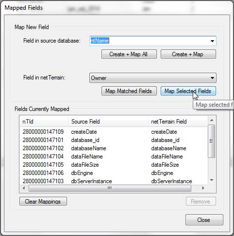
Adding a new mapped field
When many of the fields in the source match the names of the fields in netTerrain, you can map them all in one simple process by clicking on the ‘Map Matched Fields’ button.
You can also clear all mappings from the connector by clicking on the ‘Clear mappings’ button.
Any changes in the mapping will be reflected in the corresponding connector table view but notice that if the connector view is currently active you may need to refresh the view. Also, to see the values associated with the new mapped field you must run a device discovery first (see below).
3.4.1.2 Mapping fields when they don’t exist in netTerrain
As mentioned before, in case one or more of the source fields do not yet exist for the type in netTerrain, you can map and create them in the catalog, at once, straight from the ITK.
To map and create just one field from the source, select it first from the drop-down list, and then click on ‘Create + Map’ button. If you want to Create and map all the fields in the source, click on the ‘Create + Map All’ button.
Notice that these options are not available for device connectors.
3.5 Device discovery
Once the connector is properly configured the fun part begins. To run a discovery for the first time simply go to the ‘Discovery’ menu and click on the device connector you configured in the previous step.
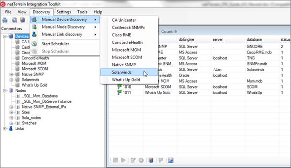
Initiating device connector discovery
Tip:
You can also start a discovery by double clicking on the connector entry and then clicking on the ‘Refresh List (Discover)’ button, as displayed below.
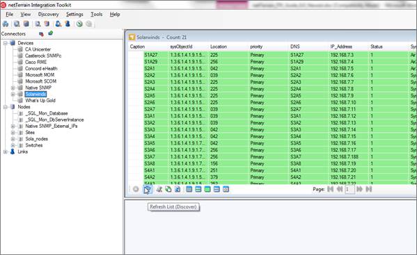
Running a discovery from the connector view
By clicking on this submenu, netTerrain will start the process of importing the raw data from the third-party data source and will display the results under the corresponding view menu. Note that the devices are not yet imported into netTerrain. The latter involves the execution of the reconciliation process. The output window will also show the start and end times of the discovery process.
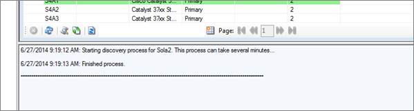
Discovery process messaging in output window
As opposed to discovery with SNMP, WMI and IPMI where the ITK has to actually poll the network, all other processes are usually fast. In certain cases though, the discovery could take several minutes:
- The source is on a slow network.
- The amount of data to discover is extremely large (tens or hundreds of thousands of records).
- The query that pulls the records from the source is very complicated or badly designed.
In sum: mind the network connectivity, preferably filter any unwanted data in the source and make sure that the source data is not using an inefficient query.
3.5.1 Viewing the results
Once devices have been imported as raw data into netTerrain, you can view these devices and associated columns by clicking on the ‘View’ menu and the corresponding device connector, or by double clicking on the connector in the connector list.
List of discovered devices
Each device will be represented by a row and will contain values for several columns that will depend on the tier-1 connector backend setup.
The list view uses specific color codes to identify the status of the device in netTerrain. We will review these color codes later in this chapter as well as some tricks and tips on how to analyze the results.
Devices can also be viewed from the tree view. In addition, if a user wants to view a device in more detail, by double-clicking on the row entry the ITK will display a dialog box with each attribute for the device.
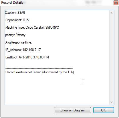
Device details
3.6 Device reconciliation
So far, the discovery has simply pulled the data from the source into a raw table in the ITK, but it is not yet in netTerrain. To import devices into netTerrain, we need to reconcile the discovered items with the netTerrain database. This reconciliation process includes the insert, update and/or delete of devices from the data source into netTerrain, according to the rules specified in the device connector mapping settings.
The ITK can reconcile devices in two different ways: create a specific device type in netTerrain based on some sort of type identifier available in the source data or create a generic device type in netTerrain. The obvious advantage of providing specific type information to netTerrain is that we can take advantage of the netTerrain catalog and automatically create the slots and ports of the devices as well as obtain the size, power and other specs of the device. That is, the ITK will create these devices automatically and they inherit all the good stuff from the netTerrain catalog.
If we want specific device types to be created in netTerrain we should make sure that the types are properly mapped. This is known as ‘Type mapping’. By default, if during the reconciliation process, there is no proper way of knowing which specific type a certain device is, the ITK will create an instance of a generic type in netTerrain. However, we can prevent the ITK from creating a device in netTerrain unless the type is mapped and force a ‘device reconciliation’.
3.6.1 Type mappings
In order for device reconciliation to work for a given device, a type mapping is required between the name of that device type in the source and netTerrain. This type mapping process enables the ITK to determine the netTerrain type a device needs to be mapped with. So, for example a device type in the source may be called Cis_6509, which could map to the corresponding Cisco 6509 in the netTerrain catalog.
3.6.1.1 The role of the object identifier
In one of the tips above we mentioned the object identifier as the recommended source field to identify the device type. Let’s review this again.
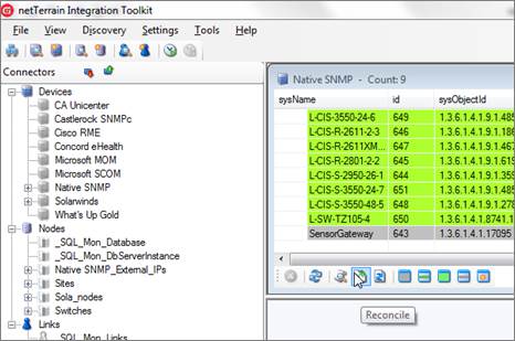
Usually the most accurate descriptor of a device type is the system object id (called sysObjectId, sysOID or just OID). The OID is a so-called MIB value that many systems (including netTerrain itself) can discover via SNMP and it uniquely identifies the make and model for a device. Conveniently enough, the ITK includes a table that maps OIDs to potential netTerrain types, as described below
Later in this guide we will review the sysObjectId as part of our native SNMP discovery engine, but it is important to note that many device connectors can also have this field available. The advantage of using this field not only lies in the fact that it ensures a univocal identification of the device type, but it can also be used as a hint to find what is the most likely type in netTerrain that matches that OID.
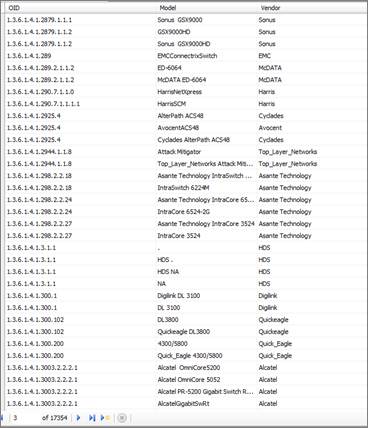
Embedded OID to type suggestions table
As mentioned before (and shown in the screenshot above), the ITK includes a table with several thousand OIDs and the most likely make and model it is associated with. By taking advantage of this embedded table, you can speed up the process of finding the netTerrain type that should be mapped with the OID.
3.6.1.2 Viewing existing type mappings
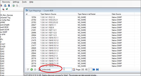
To view the list of existing type mappings, click on Settings->Type mappings->View.
The ITK includes a few thousand mappings that are used for the native SNMP discovery. To filter the mappings for a specific device connector, simply type the name of the connector into the filter box and press enter.
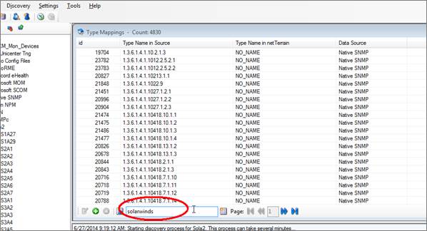
Using the filter text box
To clear the filter, click on the ‘Clear filter’ button next to the text box.
Tip:
The list view filter can use a NOT (!) operator. This comes in handy when trying to exclude type mappings for a certain connector. For example, to exclude all mappings associated with the Native SNMP, you can type ‘!SNMP’ in the filter.
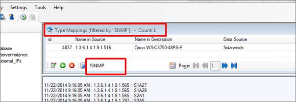
Using the ! operator in filters
3.6.1.3 Adding new type mappings
To add a new mapping into the system, click on Settings->Type Mappings->New (or Ctrl-N). A type mapping needs to specify the name of the type used in the source and the corresponding (exact) name used for the same type in netTerrain. Finally select the device connector this mapping refers to.
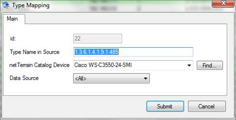
Using the type mapping dialog
In many cases the type mapping can be utilized for many different connectors, such as the case of the sysObjectId, which is a universal representation of a make and model. In those cases, you may want to assign the Data Source to all connectors. This not only comes in handy to assign a mapping to any existing connectors in the ITK (thus avoiding potential repeated work), but it will also apply to any future connectors that have a match with the source type.
To simplify the process of mapping a type, this dialog includes a ‘Find...’ button, which opens a type finder utility that can be used to search through different types in netTerrain without having to rely on the type drop down field.
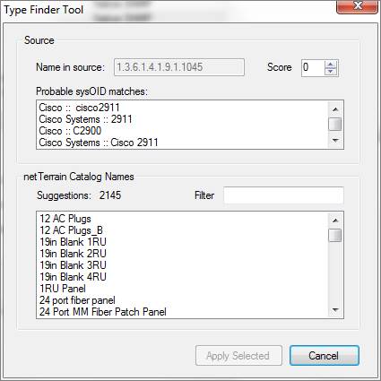
Type Finder Tool matching for a sysOID
The type finder tool can be used in multiple ways. If the source type is an object identifier, netTerrain can suggest what type the OID corresponds to, using the embedded OID to type suggestions table. This feature works automatically when netTerrain finds a match between an OID and an entry in that table. It will then display a list of one or more values in the ‘Probable sysOID matches’ section. The support table contains one or more labels by which a given OID has been referenced by other systems or vendors in the industry (hence the reason why there can be multiple choices). With a set of possible matches available, the user can start typing a search string in the filter text box and the type finder tool will start narrowing down the options of types as the string gets more specific. Another option is to use the score counter, which starts narrowing down the options in the netTerrain catalog names section by increasing the matching score.
It is possible that a certain sysOID has no match in the suggestions table or that the name in the source is not an OID at all, but an actual human readable name. In those cases, the user can still use the filter option to search for a possible match. Just type in some relevant string that could match the type name in the source and the ITK will narrow down the options.
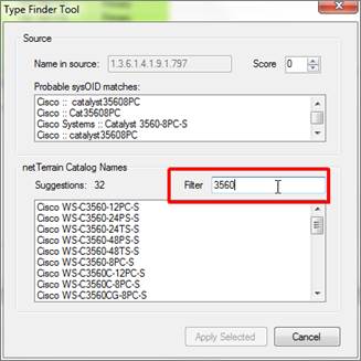
Using the filter in the type finder tool
3.6.2 Preventing device imports without a mapped type
As mentioned above, by default the ITK will create a generic device type for any device that has no identifiable type (no mapped type). However, we can prevent the ITK from creating a device in netTerrain unless the type is mapped and force a ‘device reconciliation’.
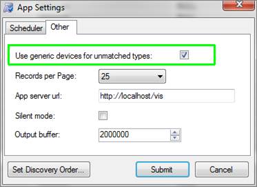
The Application settings dialog (ctrl-h) includes a tab where the user can uncheck the option ‘Use generic devices for unmatched types’, as displayed below. Unchecking this option will prevent the ITK from creating devices with unmatched types and will force the user to have to map a type for those unmatched types to import them into netTerrain.
3.6.3 Previewing a reconcilation process
Before importing and reconciling the data into netTerrain it is recommended to run a preview task. This will provide some insight into which devices will be inserted, updated or deleted. It will also provide a snapshot of devices that cannot be reconciled because no types have been mapped. The latter information can be used to add types to netTerrain or map existing netTerrain types with one of the device connector fields.
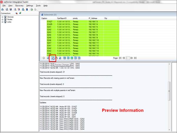
Previewing the reconciliation
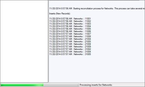
The output window will display the expected operations and records affected by a reconciliation process.
The insert operations (the ‘Insert New Nodes’ option in the reconciliation section of the connector must be enabled) include:
- Records without a matching type in netTerrain: these are all the devices for which no source type information (make and model) has been matched with a type in netTerrain. In the event of a reconciliation, these records would create a generic device type in netTerrain (or skip the insert process if the ‘Use generic devices for unmatched types’ is unchecked.
- Records that are expected to be successfully inserted.
- Records with a missing parent in netTerrain: in case the connector uses a parent field to find the container diagram in netTerrain, any devices for which such parent cannot be matched with a diagram of the same name in netTerrain will also skip the insert process.
- Records with multiple parents in netTerrain: in case the connector uses a parent field to find the container diagram in netTerrain, any devices for which a parent value is matched with more than one diagram of the same name in netTerrain will skip the insert process. In other words, use unique names otherwise netTerrain doesn’t know which parent to choose from.
The update operations (the ‘Update Existing Nodes’ option in the reconciliation section of the connector must be enabled) include:
- Records to be updated: any records for which one or more field values have changed will be updated in netTerrain once reconciled. Notice that the output will display one entry for each field that has a change. For example, if a certain device has three changes in three fields, then the output will display three entries.
The delete operations (the ‘Delete Existing Nodes’ option in the reconciliation section of the connector must be enabled) include:
- Records to be deleted: any records that were inserted by that same connector in netTerrain in some previous operation, which are no longer in the source database will be deleted in the event of a reconciliation.
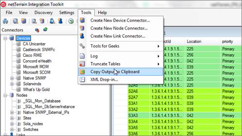
3.6.3.1 Copying the output window contents to the clipboard
If you need to work with the output window results in some other application, you can copy the contents:
- Right click on the output window
- Select all
- Hit Ctrl-C
- Paste the clipboard contents to the application
You can also copy the output window contents by clicking on Tools->Copy output to clipboard and then pasting the clipboard contents to the application.
Copying the output window contents to the clipboard
3.6.4 Reconciling data with netTerrain
Once you are ready to reconcile the data into netTerrain you can start the process by simply opening the list view for the connector and clicking on the ‘reconcile’ button.
A single button to discover and reconcile is also available (next to the reconcile button).
Reconciling data with netTerrain
Once the reconciliation starts, the ITK will display the same output displayed for the preview, with the actual devices being inserted, updated and /or deleted.
Note that for large bulk imports, this process may take several minutes or even hours as devices are properly imported, reconciled and indexed. For convenience, as the ITK is processing the reconciliation, a progress bar will be displayed on the bottom status bar of the application window.
ITK progress bar
Once the reconciliation has finished, any devices that are ‘type mapped’ and have the proper container diagram information (either a default diagram or parent node that exists in netTerrain) will be created in netTerrain. If no rack units were mapped, each device will be placed sequentially on its corresponding diagram, starting from the top left corner of the netTerrain screen.
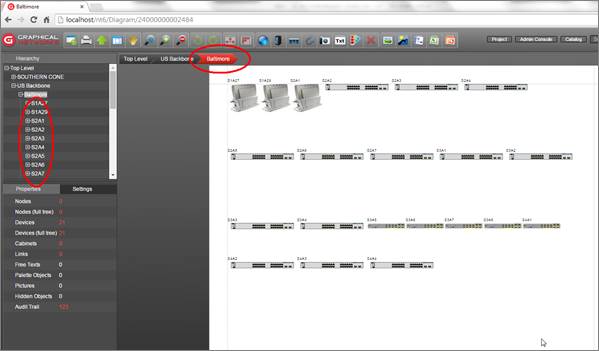
Devices imported into netTerrain
Attention!
When a discovery or a preview/reconciliation process is running (whether triggered manually or through the scheduler) you cannot start another process. Attempting to do so will yield an error as seen on the screenshot below.
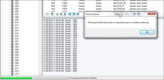
Warning message for an attempt at concurrent discovery
3.6.5 Mapped fields missing in netTerrain
For device connectors, the ITK tries to match up mapped fields based on the mapping specifications, but it assumes that the field in netTerrain exists. This could present a difficulty for device connectors (not for node connectors since the mapping is against a particular type), because for device connector the reconciliation involves all types. A certain field may exist for certain device types in netTerrain but could be missing for others. For example, a field called IOS may exist for all Cisco types in the netTerrain catalog but not be available for Juniper types. As a consequence, you may find instances of reconciled devices in netTerrain that do not have a field that you expected to see, based on the mappings done in the ITK.
In some cases, this may not be a problem because the field wasn’t needed for that type to begin with, but what can we do if it was indeed needed? You can obviously go to the netTerrain catalog and add the field for all the types that are missing it. This could present a headache if the field is missing for hundreds, let alone thousands of types.
For such cases the ITK has a feature to add a certain field to every device type in netTerrain. This feature is mostly intended for usage with the SNMP discovery, so it is somewhat buried in the UI (a command is also available). Follow this 3-step process:
1) Go to Settings->Monitor->Configuration (or press Ctrl-G) and click on the ‘Add single field’ button
2) Type in the name of the field you want to add to all types in netTerrain
3) Click ‘OK’
The ITK is smart enough to only add the field to the types that are missing it. And yes, be patient indeed, this process can take a couple of minutes.
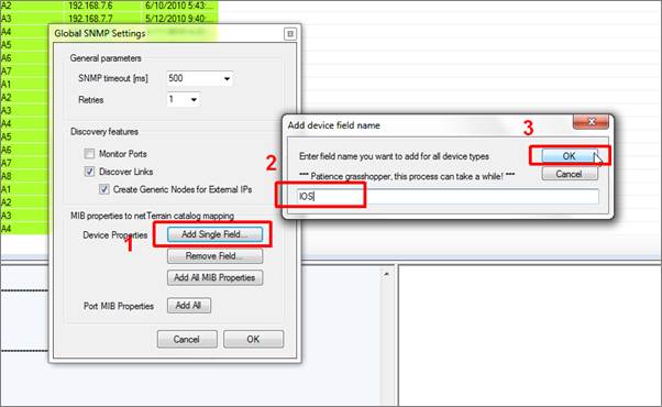
Adding a field to all device types in netTerrain
You can also remove a field from all types in netTerrain, using the ‘Remove Field’ button. We will review the rest of the functions in this dialog in the chapter about Monitoring.
Attention!
Be careful with these functions as they affect all types and instances in netTerrain!
3.7 Automating the process
The entire process described in the previous sections can be automated so that it runs in the background, without a user having to manually start the discovery and reconciliation every time data needs to be synchronized between the sources and netTerrain.
3.7.1 Setting up the scheduler
The scheduler consists of two main attributes:
- Polling cycle: deals with the frequency of state information (status) update for devices that have already been imported into netTerrain and that exist in the original data source
- Discovery cycle: deals with the frequency of the insert/update/delete process that reconciles the data between the data source and netTerrain
To set up the scheduler go to Settings->Application and proceed to modify the Polling Cycle and Discovery cycle parameters based on how often the ITK needs to update the information in netTerrain.
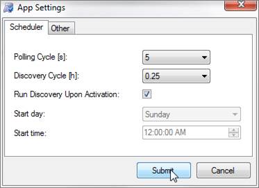
Setting up the scheduler
You can set the scheduler to run immediately upon activation, or to only start at a specified weekday and time. If you check the ‘Run Discovery Upon Activation’ option, the ITK will start immediately after you click on the ‘Start Scheduler’ button (see below). If this option is unchecked, after you click on the ‘Start Scheduler’ button the scheduler will start on the specified day and time and then fire up based on the frequency set in the ‘Discovery Cycle’ combo box. For example, a setting matching the screenshot below would mean that the scheduler will start on Tuesday at 3AM and then trigger every 24 hours (Wednesday 3AM, Thursday 3AM, etc.).
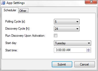
Using the scheduler day and time settings
Tip:
It is recommended to set the discovery cycle to a value that is high (such as 24 hours) to avoid excessive SQL traffic. In general configuration data does not change often enough to require a refresh on the netTerrain inventory in real-time or near real-time. In many cases it is not even necessary to automate the discovery, since a manual process can be triggered once a day or even once a week.
3.7.2 Real-time status polling
As we saw above, one of the parameters in the scheduler is the polling cycle. This cycle essentially determines how often the ITK will update status (or state) values for any connectors that support it.
To enable status updating, the device connector itself needs to be able to pull state information from the source, which, of course, means that the source needs to be able to obtain real-time state information in the first place.
Note that the status polling we refer to here is status available from the original data source, not live status obtained from the actual devices. The latter is also possible using the ITK SNMP discovery tool (see the chapter on SNMP discovery).
3.7.2.1 Mapping the status field in the source
Assuming the source does indeed provide real-time status information for devices (such as Solarwinds, for instance) you need to map the field that pulls that information. To do this, follow these simple steps:
1) Make sure the status field in the source is already part of the mapped fields, so that netTerrain can import that data.
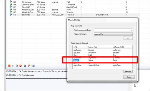
2) Right click on the device connector and select ‘Status Mappings’
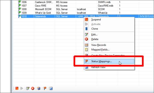
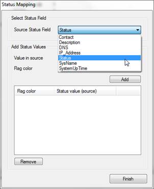
3) From the Status Mappings select the status field from the source in the drop down
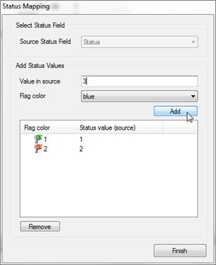
4) As an optional feature, you can also set flag colors representing different status values for each record in the ITK list view. These colors do not have any effect on the representation of the devices in netTerrain. To actually change colors (or effects) for the visual representation of devices in netTerrain, you can create visual overrides in the netTerrain catalog (see Power User Guide).
Below is an example output using that shows records from the source along with the corresponding flag colors.
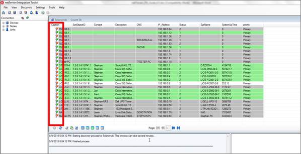
Status mappings associated with discovered records
3.7.3 Discovery order and passes
In some cases, you may want to specify the order by which the ITK will process the discovery and reconciliation of the connectors. This can be useful in cases where one connector may have a dependency with another. For example, if one connector discovers sites and another one discovers devices that will be placed under sites, which are discovered by the first connector, then you want to make sure the ITK first processes the sites and then the devices to avoid potential errors related to missing parent objects.
To specify the order of how connectors are to be processed by the ITK, follow these simple steps:
1) Go to the Settings menu -> Discovery Order
2) In the ‘Discovery Order’ dialog you will see a list of all the device and node connectors that currently exist in the ITK
3) Select the appropriate connectors and move them up and down in the order hierarchy using the green and blue arrows
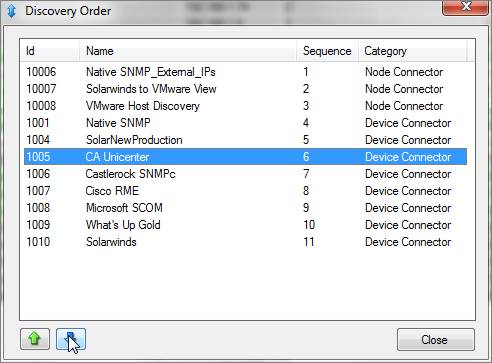
Setting connector discovery order
Attention!
Notice that link connectors (see chapter 5) are missing from the list. Link connectors are always processed last in the ITK. This ensures that any dependencies with nodes are always accounted for by discovering the nodes (or devices) first. Since links can have no cascading effect on other links or on nodes, specifying their discovery order would have no effect in the overall process.
In addition to the discovery order, you can also specify the number of times in a row a connector should be reconciled when the scheduler is running (also called “passes”). This can be useful when a specific connector has recurrent dependencies, such as for the parent ancestry. For example, if a site connector uses a parent locator field, which may expect other sites to exist and those sites may be imported from that same connector, then you may need to run the connector more than once. Since only nodes can server as parents of other objects, this feature is only applicable to node connectors.
As we would expect, the default number of passes is 1. To change that, go to the node connector list, select a connector, and then change the number of passes by using the ‘+’ and ‘-‘ buttons, as depicted below.
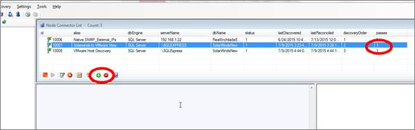
Changing the number of “passes” for a connector
3.7.4 Starting the scheduling process
After the scheduler has been configured, you can start the automated discovery and reconciliation process by simply clicking on the ‘Start Scheduler’ button, as shown below:
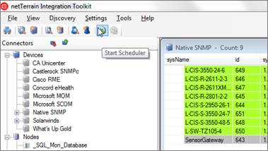
Starting the scheduler
This automated process will cycle through any device connector that is set as active and run a discovery from the source and reconciliation process against netTerrain. The ITK will then insert, update and delete devices, depending on how device connector was configured in the reconciliation tab.
Attention!
If one or more connectors are not reconciling when the scheduler is running, make sure these connectors are set as ‘Active’ (see below).
3.7.5 Activating connectors
Sometimes you need to run a limited set of connectors without the rest being processed. For each connector in the ITK there is a flag that can be set to active (green) or suspended (gray). When using the scheduler, only connectors that are set as active will execute.
To set a device connector as active, click on the device connector list menu (Ctrl-A) and from there select the device connector and click on the ‘Activate’ button (or right click->Activate). To suspend it, use the ‘Suspend’ button, as shown below.
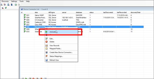
Activating a connector
A command to activate and suspend all device, node and link connectors at once is also available (see the commands section at the end of the guide).
3.8 Analyzing the results
After the information has been discovered and reconciled into netTerrain we may need to do some discrepancy analysis or error checking, so it is important to know how to manipulate and analyze the results displayed in the ITK connector tables.
3.8.1 Device states and their corresponding color codes
As we mentioned earlier in the guide, the process of importing devices into netTerrain consists of two parts: the discovery process, where the connector reads the data from the source and dumps it into a raw table in the ITK and the reconciliation process, where the devices are inserted, updated or deleted in netTerrain. As such, a device can be in four possible states:
1) The same device (i.e. a device with the same name) also exists in netTerrain and it was discovered and reconciled into netTerrain by that same connector. Such devices have a lime fill color, as shown below.

2) The same device also exists in netTerrain, but it was created manually or it was discovered and reconciled into netTerrain by a different connector. Such devices have a green fill color, as shown below.

3) The device in the connector table is currently not in netTerrain, but the type has been mapped in netTerrain so a reconciliation process (barring any parent issues) would create it in netTerrain. Such devices have a plain white fill color, as shown below.

4) The device in the connector table is currently not in netTerrain and the type has not been mapped, so a reconciliation process would create a generic device type in netTerrain (or yield an import error if the ‘Use generic devices for unmatched types’ application setting is unchecked). Such devices have a gray fill color, as shown below. Note that after a reconciliation process, any grey devices that do indeed trigger the creation of a generic device would now exist in netTerrain, hence be displayed in lime.

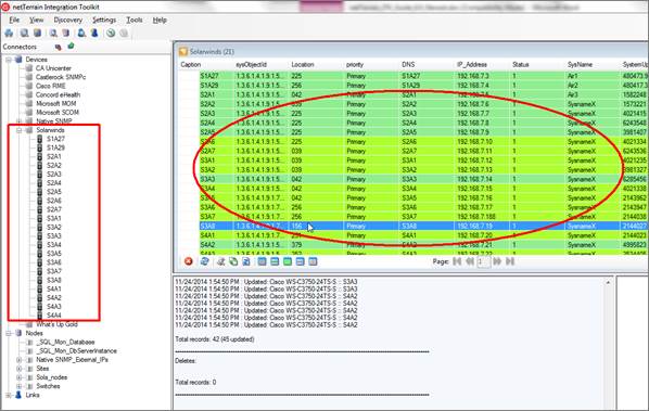
Below, we show an example of devices imported from a Solarwinds device connector, with different color codes based on the status of the discovered devices in netTerrain.
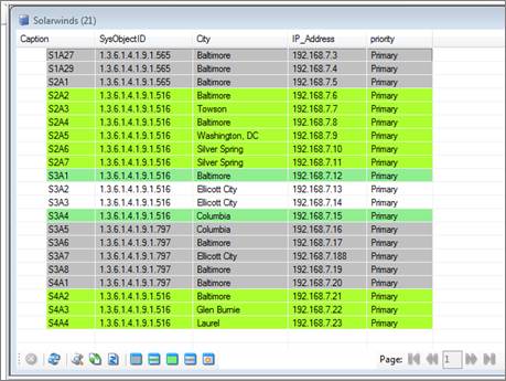
Device color codes
Attention!
Device color codes can be driven by changes in the source data, but also changes in netTerrain. For example, if a user changes the name of a device in netTerrain or deletes a device in netTerrain, this can trigger a change in the color code in the ITK. Make sure to refresh the page in the ITK to make sure you are reflecting any recent changes in netTerrain (see below).
3.8.2 Refreshing views
To make sure your ITK view is reflecting the latest data you can refresh a list by right clicking on it and clicking on the ‘Refresh’ option (or F5).
Refreshing a view
3.8.3 Filtering devices based on color code
The ITK device connector views have a series of filter buttons that can be used to filter data based on the state of the devices in netTerrain. These filters include the following options:
- Only show devices not in netTerrain and without a mapped type (gray).
- Show all devices that have a mapped type in netTerrain (lime, green and white).
- Only show devices that exist in netTerrain (green and lime).
- Only show devices that do not exist in netTerrain (gray and white).
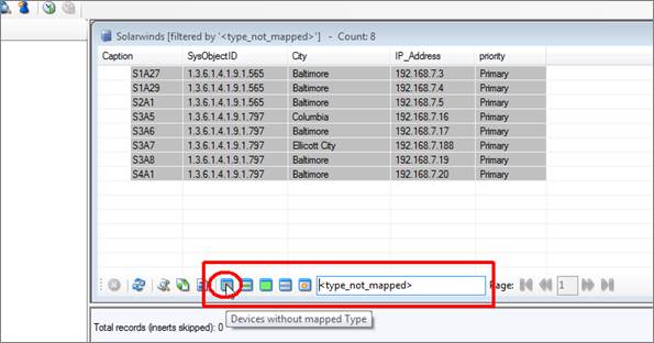
Using device color filters
Notice that when using a filter, the ITK automatically appends a value in brackets in the filter text box. In essence these filter buttons are simply applying a command to the filter text box and executing it.
To clear the filter, simply click on the ‘Clear Filter’ button next to the filter text box, as shown below.
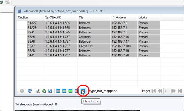
Clearing a filter
Tip
An easy way to map types for any devices that are currently unmapped (gray) is to use the first color filter and then map the types directly from the view (see below).
3.8.4 Mapping types from the device view
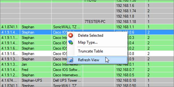
Any unmapped device types in the ITK can be mapped directly from the device view by right clicking on the device (should be depicted with the gray fill color) and clicking on ‘Map Type’, as shown below.
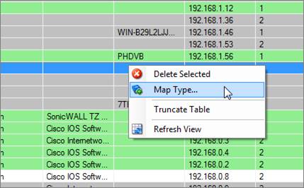
Mapping a type directly from the device view
3.9 Logs and data purging
The ITK generates a log for most processes that affect data, such as discoveries, reconciliation processes and commands, as well as all errors that can occur in the system. A separate log file is created for each day, to prevent the log file from growing too big.
To access the log, click on Tools->Log->Open (or Ctrl-L). This will open the most recent log file available. The log files are usually opened with a default text editor like notepad. To access older log files, you need to open them from the application server directly, usually in ‘C:\ProgramData\Graphical Networks\netTerrain\ITK\Logs’.
Log files may also be purged. A command is available for that, but it is easier to just purge them by clicking on Tools->Log->Purge.
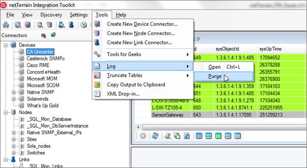
Purging the ITK log
Attention!
When you purge the logs, all log files are removed from the log folder, not just the log for the current day.
The log file includes data such as an entry description, IP address, process description, start of process, thread number and timestamp.
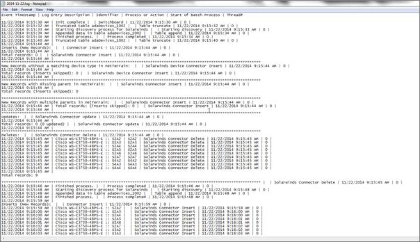
Log file
3.9.1 Truncating (or purging) connector tables
Discovered data can also be purged from the ITK. This process will only truncate the intermediate ITK tables containing the discovered data. It will not delete data from the source or from netTerrain. You may want to purge connector data to start a process from scratch, or to remove data from netTerrain (see tip below).
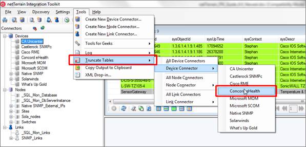
To truncate connector data, go to Tools->Truncate Tables and select the appropriate connector you want to truncate.
Truncating connector data
Another way to truncate a table is as follows:
-
Go to the connector list view
-
Right click on the view
-
Click on ‘Truncate table’
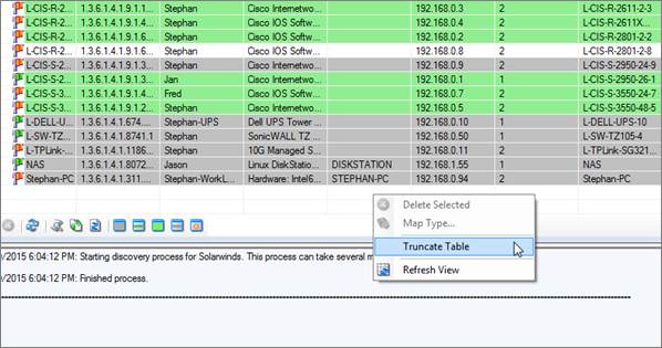
Truncating a table using the right click context menu
Tip:
A simple way to remove all records from netTerrain that were discovered by a given connector, is to first truncate the table in ITK and then reconcile the data. Be careful with this process, as you will not be able to recover the data in netTerrain unless you restore the database from its previous state or you reconcile the connector with the same discovered data that existed before the truncate process took place.
Also take into account that in order to delete records in netTerrain from the ITK, that connector needs to have the ‘Delete devices without matches’ option set to ‘Yes’.
3.9.1.1 Truncating all device tables
In some cases, you may want to truncate all device tables, whether it is to recreate a process or to remove all devices from netTerrain. To truncate all devices for all connectors, go to Tools->Truncate Tables->All Device Connectors.
4 Creating custom device connectors
In addition to the list of built-in device connectors, netTerrain also allows you to create new device connectors for any third-party data source that uses a SQL Server, Oracle, PostgreSQL, MySQL or MS Access backend database.
If the data is stored in a different database engine or file format, an indirect method using a ‘proxy database’ is also possible. We discuss this method later in the guide.
Overall, the process for creating a new custom device connector is very similar to a tier-1 connector and the same features for discovery, reconciliation and data analysis apply.
4.1 Prerequisites
To create a new device connector, netTerrain must know certain aspects of the data source, such as connection properties, the table or query to import the data from and the fields that will be mapped to custom fields in netTerrain.
4.1.1 Proxy or source database?
The first step in creating a device connector requires understanding what the database engine for the source data will be.
The ITK can currently read from SQL Server, PostgreSQL, MySQL, Oracle and MS Access (jet) databases. If the source data resides in one of those three engines, then the connection string is easy to create by simply filling out the appropriate connection information in the device connector creator dialog.
In many cases though, the source information may be another database engine or a text file. In those cases, a device connector can still be created by means of a so called ‘proxy database’.
Some of the built-in device connectors, such as the Cisco RME device connector, use this mechanism, which is depicted below.
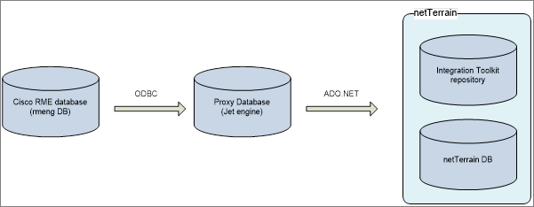
Architecture of the Cisco RME device connector using a proxy database
In the example above, the intermediate database acts as a proxy for the source database, since the ITK does not have the capability to create a connection string directly into the Cisco RME database engine.
Other common examples of proxy settings include text files and comma separated values (csv) files that are exported as individual files by another system, to be imported automatically into the ITK. Countless such text or csv outputs have been used in netTerrain implementations where a non-database format output needs to be automatically synchronized with netTerrain node and link data.
4.1.1.1 Proxy set up use-case: OTDR readings
As an example of a text file input using a proxy, consider the following scenario common in netTerrain OSP applications: an Optical time-domain reflectometer (OTDR) that outputs a result to a text file. These text files are typically placed in a fixed drive location which, via a proxy connection, are linked to one or more ITK connectors mapped to the corresponding netTerrain entities (for example, a fiber trunk or strand). The ITK then updates a property of choice (such as OTDR reading) on that fiber, which can be used to point the location of a possible fault.
The proxy database can be any of the engines the ITK supports natively, such as Microsoft SQL Server. It is up to the user to create the connection between the proxy and the source, and this method may depend on the computer configuration where the proxy will be set up. To not leave you hanging, we will provide two examples of proxy database settings using Microsoft SQL Server and Microsoft Access.
Below, we discuss specifically how to create a custom connector using a proxy database by means of a SQL Server proxy and an MS Access proxy.
4.1.1.2 Setting up the proxy database using SQL Server
In the following example we will set up a proxy database using SQL Server. We will assume the source is some csv data, as depicted below.
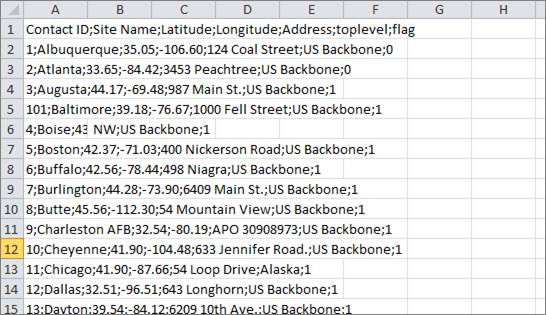
csv sample data to be imported via a proxy SQL Server database
There are a number of ways of setting up a proxy in SQL Server that will update the source data as tables or queries in SQL Server, including Linked Servers and DTS/SSIS packages. For our example we will use a more direct method, namely a stored procedure using a bulk insert. To ensure the data is up to date every time the ITK refreshes from the source, we will also automate the process of executing the stored procedure before the ITK discovers the data.
To set this up proceed as follows:
Step 1: Create (or using an existing) database that will serve as your proxy.
Ideally, we recommend this being an empty database that sits on the same engine as netTerrain. This database will just contain the stored procedures and the tables with the raw data imported from the source. Since netTerrain itself runs on SQL Server, sometimes that server (not the netTerrain database itself though!) is the most convenient place to set up a proxy, since the existence of that engine is guaranteed. Provided, of course, the DBA is nice enough to let you set up a proxy there, but that’s a different story.
Step 2: Prepare the tables in your proxy database.
This usually just means creating the tables that will hold the raw data. Make sure the structure of the database is compatible with the source columns. This means using matching names and appropriate types. Continuing with our csv example shown above we could create a sites table using the following script:
USE [CsvProxy]

GO

/****** Object:  Table [dbo].[sites]    Script Date: 06/07/2016 16:28:35 ******/

SET ANSI_NULLS ON

GO

SET QUOTED_IDENTIFIER ON

GO

CREATE TABLE [dbo].[sites](
         [Contact ID] [nvarchar](255) NULL,
         [Site Name] [nvarchar](255) NULL,
         [Latitude] [nvarchar](255) NULL,
         [Longitude] [nvarchar](255) NULL,
         [Address] [nvarchar](255) NULL,
         [toplevel] [nvarchar](255) NULL,
         [flag] [int] NULL
) ON [PRIMARY]

GO
As you can see, the structure of the table coincides with the columns defined in the csv file.
Step 3: Create the stored procedure.
The stored procedure will use a ‘bulk insert’ method to fill the raw tables we created in step 2.
For the stored procedure to work correctly, it must be able to fetch the csv data from the same place, every time it is executed. So, it is important to determine a specific location where the source files will be dumped, and not change the location after subsequent discoveries. We assume, of course, that the location of the csv is accessible for the stored procedure (both in terms of network connectivity and access permissions).
Also, the script will truncate the raw tables and fill them during every process. This is not mandatory (one could use a different method), but it is simple enough and usually not very taxing in terms of performance.
Finally, depending on the delimiters used in the csv file, the method used to successfully execute the stored procedure may vary. In our example we assume a line feed (‘char(10)’).
Here is a sample script that can be used for the stored procedure:
USE [CsvProxy]
GO

/****** Object: StoredProcedure [dbo].[FillCsvTables] Script Date: 06/07/2016 16:33:08 ******/
SET ANSI_NULLS ON
GO

SET QUOTED_IDENTIFIER ON
GO

CREATE PROCEDURE [dbo].[FillCsvTables]
AS
BEGIN

  SET NOCOUNT ON;

  DECLARE @Path NVARCHAR(255);

  SET @Path = 'C:\Temp\CsvSamples\'

  DECLARE @Rowterminator NVARCHAR(10);

  SET @Rowterminator= CHAR(10);

  -- sites table

  TRUNCATE TABLE sites

  EXEC('

  BULK INSERT sites

 FROM ''' + @Path + 'sites.csv''

 WITH

 (

 FIRSTROW = 2,

   FIELDTERMINATOR = '';'',

 ROWTERMINATOR = ''' + @Rowterminator + '''

 )')

END

GO
Step 4: Creating a dummy connector to set up the automation in the ITK
As opposed to Linked Servers (or linked tables in Access), where there is a dynamic link between the source and destination, a bulk import process pushes the data to the raw tables, which are not linked or connected to the source. This means that if the data changes in the source, the raw data in the proxy tables may be out of date. To prevent that, we make sure that right before the ITK runs a discovery, it first executes the stored procedure. This can be accomplished from the ITK itself.
We recommend making sure the ITK runs the stored procedure before anything else, so one way to ensure this is to create what we call a ‘dummy’ connector that does nothing except run that procedure and placing that connector first in the discovery order.
Create a dummy node connector by linking it to the table in the proxy database (see chapter 5 on how to create node connectors). You can use any netTerrain type, since it doesn’t matter. the connector will not reconcile any data (in fact we can add a WHERE clause statement that ensures it doesn’t even waste CPU cycles discovering anything).
Here is an example of the three connector tabs that show how to set it up:
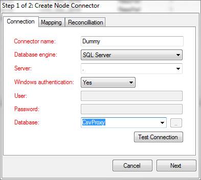
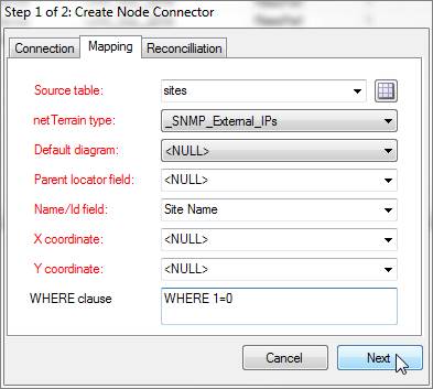
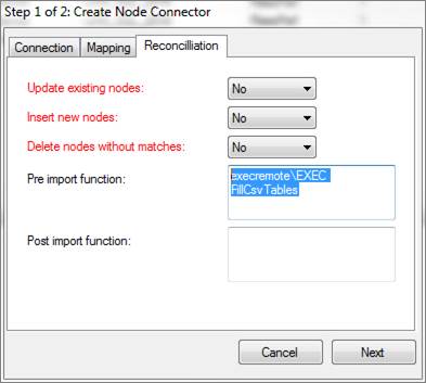
Notice two things: the 2nd tab includes a contradictory WHERE clause 1=0, which ensures no data is discovered (we don’t need it) and the 3rd tab includes a ‘pre import function’, which is the process that executes the stored procedure remotely. The syntax for that is as follows (make sure the name after the EXEC statement matches the name of the stored procedure):
execremote\EXEC FillCsvTables
Also notice that the update, insert and delete options in the third tab are set to no. Again, we don’t want any data going back and forth. The sole purpose of this connector is to execute the stored procedure.
Step 5: set the dummy connector discovery order
Finally, let’s make sure this dummy connector is the first thing to run upon an ITK scheduled task, by setting the discovery order first (please see discovery order in chapter 3).
4.1.1.3 Setting up a proxy database using MS Access
In this example we will set up a proxy database like the one used for the CiscoWorks RME device connector, using an Access database as the proxy, which in turn is connected to another third – party database engine (the target database).
The first step in setting up the proxy database is to make sure that the machine where the proxy resides has the driver to the target database engine. Once that is verified, you proceed with the creation of a Machine DSN. A DSN is usually created from Control Panel->Administrative Tools->Data Sources ODBC.
Then, follow these steps to set up the proxy database:
1) Create an empty Access Database file that can be placed under
2) Go to the tables tab and from the external data tab create an ODBC connection by linking a table to the source (this process may differ between different versions of MS Access).
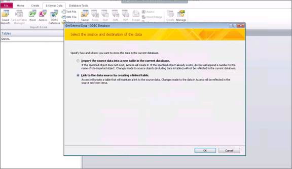
3) In the ‘Data Source’ dialog box, click on the ‘Machine Data Source’ tab and select the DSN database created before.
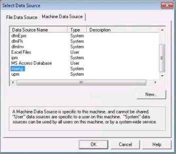
4) If needed, enter the credentials for this database.
5) From the Link tables dialog select the appropriate table or view that contains the devices that need to be imported into netTerrain.
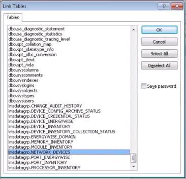
6) You may have to select a unique identifier for the view. It is not a mandatory step, since the query will not be updated.
7) Close the database.
4.2 Step 1: Creating the device connector
When creating the device connector, a 2-step wizard will guide you through the process. It is recommended to have certain mandatory and optional information beforehand, which will later have to be filled out when proceeding with the device connector creation.
To start the wizard, go to Tools-> Create new device connector. You can also start the wizard from the device connector list by using the ‘Create new connector’ button or right click context menu.
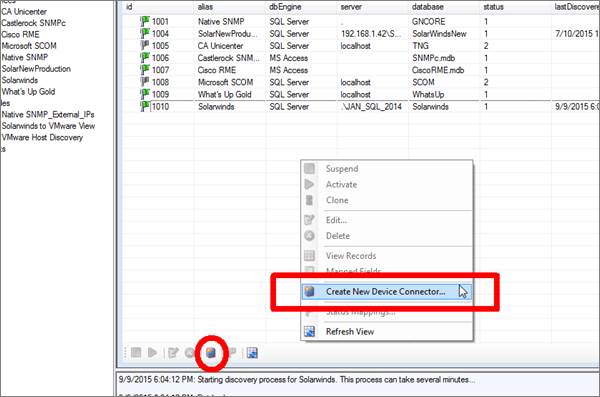
Creating a new connector
A ‘Create new device connector’ dialog window will appear, prompting you to fill out information to complete the first step in the device connector creation process. All the fields with a red label are mandatory.
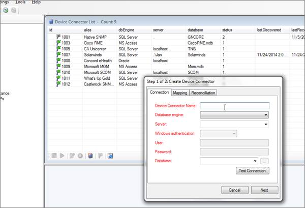
Create new device connector wizard
4.2.1 Connection information
The database related information that the ITK needs will either be in an Oracle, PostgreSQL, MySQL, SQL Server or MS Access format. The source data either resides in one of those three engines or in a different database format that communicates through an Oracle, PostgreSQL, MySQL, SQL Server or an MS Access proxy.
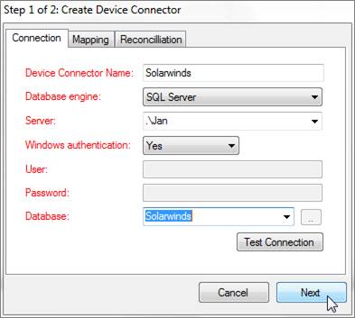
Setting up the initial connection parameters
When using MS Access as the engine, the server is not required, as the path to the corresponding MS Access file will be used. In the case of using SQL Server, the server and database name must be specified.
Database credentials are only required for SQL Server, PostgreSQL, MySQL and Oracle based device connectors. It is important to note (and a relief for any DBA) that the ITK only makes ‘SELECT’ type statements against the target database. This means that (whenever applicable), a user with read-only access to the source will suffice. Any permission levels higher than read-only will have no additional effect on the process because the ITK never writes any data back to the source.
Both Trusted connections and SQL Server authentication are supported for SQL Server based device connectors.
Attention!
For Oracle connections you may need to have the Oracle ODBC client installed, so that a TNS name can be referenced. For PostgreSQL-based connectors you must first create a DSN from the machine hosting the ITK to the PostgreSQL database, so that the DSN can be referenced in the connector.
4.2.2 Mappings tab
The mappings tab for custom connectors is essentially the same as for any tier-1 device connectors (we’ll spill the secret here and tell you that built-in connectors are in fact created using this exact same wizard). We’ll repeat the instructions specified in the previous chapter on how to fill out the mapping tab
Attention!
It is important to understand the structure of the data source you want to import data from. For example, you need to know what table or view contains the devices to be imported as well as which fields contain the unique naming convention and device type information.
Also, if you change any fields in the mapping tab currently associated with an additional mapped field (see additional mapped fields section), then the mapped field will be removed from the mapped field list.
4.2.2.1 Source table
The source table represents the table or view where the records that need to be pulled from the data source are stored.
Tip:
If you need to modify some of the data being imported into netTerrain or need to correlate more information that is available in other tables, create a view that “massages” that data for you and point the source table field to that view.
4.2.2.2 Device type field
The device type field is the data field in the source table that holds the identifier for the type of device that will be mapped with the corresponding type in netTerrain. netTerrain uses a name field in the node catalog table to identify a device type. In other words, netTerrain will try to map the type name from the source with the node type library name in netTerrain.
Tip:
The most accurate descriptor of a device type is the system object id (usually called sysObjectId or sysOID). This is the SNMP discovered unique make and model identifier for a device and can be nicely mapped to netTerrain’s existing table of OID to device type information (more on that later)!
4.2.2.3 Default diagram
When importing devices from a third-party data source, netTerrain can assign a default diagram for the device. This is especially important when the source table has no fields that can provide information about the parent diagram containing each device. This default diagram in netTerrain will serve as the initial repository for newly imported devices. You can assign different diagrams for different device connectors instead of searching for devices from multiple device connectors in one generic diagram. To specify a default diagram, at least one diagram needs to exist in netTerrain beforehand.
4.2.2.4 Parent locator field
An alternative to using a default diagram is to automatically place devices under a specific parent object. This is possible if the source table contains a field that stores that parent ancestry data. This can be specified in the parent locator field.
Attention!
In order for the automatic placement to work, the parent diagrams must exist in netTerrain prior to importing the devices. We recommend creating a separate connector that pulls the parent objects in advance, which will then guarantee that the devices will be placed under the corresponding parent objects. This is yet another way to further automate your network documentation process.
4.2.2.5 Name field
The name field should contain the name or unique identifier for each device, and it will be mapped to the name field in netTerrain. Technically, it is not necessary for this field to pull values that are unique, but it is highly recommended. If the name field is mapped to a field in the source table that does contain repeated values, then any devices with the same name field value will throw an error during the update process. Also, if devices do not have unique names in netTerrain, then if later on you decide to also import links using the ITK, any links that have any repeated devices as endpoints will not be imported.
4.2.2.6 Rack position field
Rack coordinates can be used to automatically place devices on a given rack and rack unit. In other words, this field can be used to import rack positioning information from the source data and avoid placing a device on a rack manually. Naturally, this requires the source data to contain the proper rack unit information for the imported devices. This field assumes that the parent for each device is a rack and is specified in the parent locator field. To summarize, the rack positioning in the ITK must comply with the following:
- The parent object type must be a rack and must exist.
- The source table must contain a field for the rack unit.
- The rack unit for each record in the source data must be consistent with the size and rack unit availability for the corresponding parent rack.
If no coordinate information is available, use the
4.2.2.7 WHERE clause
The last field of the second tab contains a WHERE clause. This can be used as a mechanism to filter certain records from the source table. The syntax of the WHERE clause must correspond to the flavor of SQL that the source database uses and must start with the ‘WHERE’ keyword (see the screenshot for an example).
Attention!
If the syntax in a WHERE field is incorrect, the discovery process will fail. When writing the clause, you must start the filter with the ‘WHERE’ keyword itself (for example ‘WHERE location=1’). Also, mind that SQL syntax as it may differ from different database engines. SQL Server uses T-SQL, Oracle uses PL/SQL and PostgreSQL, MySQL and MS Access have slightly different flavors of SQL as well, so there may be minor differences in the syntax. If you want to avoid all this hassle don’t use the WHERE clause and instead connect to a custom view where the information is already pre-filtered.
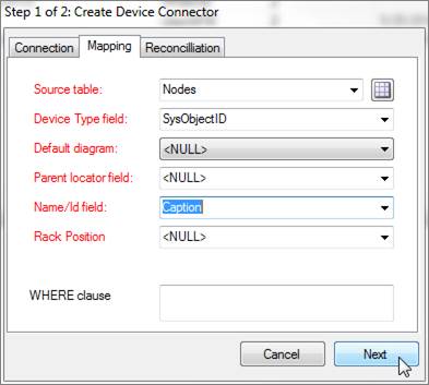
Mappings tab settings
4.2.3 Reconciliation settings
The last tab deals with the mechanism for device reconciliation into netTerrain.
4.2.3.1 Updates
If you want to update any field changes for devices that already exist in netTerrain, then set the ‘update existing devices’ combo box to ‘Yes’.
4.2.3.2 Inserts
New devices that do not exist in netTerrain and were discovered by the device connector will be inserted into netTerrain, if the following criteria apply:
- The ‘Use generic devices for unmatched types’ application setting is checked or the device type can be mapped to a type in netTerrain (see type mapping)
- A default diagram has been assigned for the device connector (defined in the mappings tab) or a parent container field exists, and the proper parent object also exists in netTerrain
- The ‘Insert new devices’ combo box is set to ‘Yes’
4.2.3.3 Deletes
Devices that exist in netTerrain but no longer exist in the source can be processed in two different ways:
- They can be deleted from netTerrain by setting the ‘Delete devices without matches’ combo box to ‘Yes’
- The can be kept in netTerrain by setting the combo box to ‘No’
Attention!
When the ‘Delete devices without matches’ combo box is set to ‘Yes’ only devices that were originally inserted by that same connector will be deleted from netTerrain. For instance, a router called ‘123’ that no longer exists in the data source but still exists in netTerrain, will only be deleted if it was originally inserted by that same connector. Internally, any devices that are inserted in netTerrain by the ITK are tagged with the connector id. Then, when a delete process occurs, only devices with that connector id will be deleted (provided they no longer exist in the source).
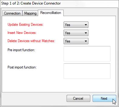
Reconciliation tab
4.2.3.4 Pre and post import functions
These fields are used to place advanced functions that are processed before and after an import occurs. An example of a pre-import function could be a call to execute a stored procedure in the source data, which massages the records to be imported. An example of a post import function could be a layout algorithm that is triggered after the import to automate node positioning.
Attention!
The Pre and Post import function fields are currently reserved for Graphical Networks consultants. If you think you need a function to perform a specific action, please enter a ticket in the support portal.
4.3 Step 2: Mapping additional fields
A list of additional fields that need to be imported from the table can be specified and mapped to the corresponding fields in netTerrain, just as we saw in the previous chapter for built-in device connectors. This is done in step 2 of the wizard.
Enter each field by specifying the name of the field in the source table or view and the field that it should be mapped to in netTerrain. For convenience, a button that maps all matching fields is included. This comes in handy when the source and netTerrain fields have the same name.
Attention!
The Create field options are not available for device connectors mainly because device connectors are not mapped to a type, so those fields would have to be created against all device types and the catalog. We prefer you to do this instead of assuming all fields need to exist for all device types.
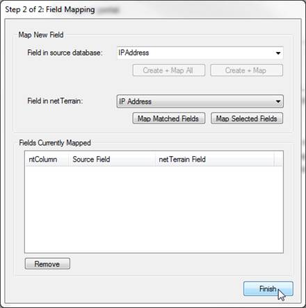
Field mapping dialog
Click on the ‘Finish’ button to register the connector.
Attention!
If the registration is successful, this does not necessarily mean that data will be imported successfully into netTerrain. Run a test a discovery process first to see if the records are being imported from the source as expected. If the connector creation process fails, please contact support@graphicalnetworks.com or enter a ticket in the support portal.
4.4 Tying it all together with an example
We’ll review what we have learned so far this chapter by creating a device connector from scratch to a well-known monitoring tool called Solarwinds NPM. Our assumptions are the following:
-
The source resides on a SQL Server database (to keep it simple we have it on our local machine).
-
We know that we can connect to the database via the Windows user.
-
Also, we know that the device information sits in a table called ‘Nodes’.
-
The devices table has a field called ‘caption’ that uniquely identify devices in this database.
-
The table also has a sysObjectId field that identifies the device types.
-
Additional fields of interest include: IP_address, DNS and Last_Boot.
When building this device connector, we would like to mirror the information in netTerrain exactly how it resides in the source database. That is, all new devices discovered from the source should be inserted in netTerrain, and any other changes, such as updated fields, should be in synch with netTerrain. We would also like to remove devices in netTerrain that no longer have a match in the source database.
This is how we would set up the device connector in Step 1:

Step 1, first tab
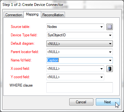
Step 1, second tab

Step 1, third tab
Note that we chose a diagram called ‘Baltimore’, which is an existing diagram in the netTerrain project, to place all newly discovered devices, because the source database does not have a reliable data field that can tell us the parent location for each device.
In Step 2, we can add the following fields to our list of mapped fields.
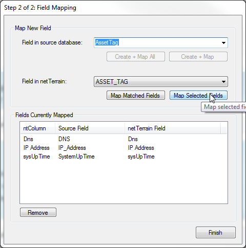
Notice how the field in the source may not match exactly the name of the mapped field in netTerrain. Also notice that fields that were used in step 1 are not available in step 2.
4.5 Next steps
Once the ‘Finish’ button is clicked, the device connector should be registered in the ITK database and force an application restart:
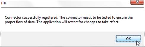
At this point the user can verify the device connector entry by looking at the device connector list.
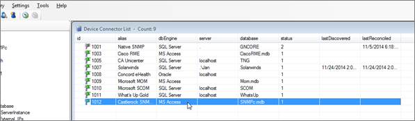
New device connector in list
As mentioned earlier, just because the device connector has been successfully registered does not mean that it will work correctly. Some factors that could affect the proper functioning of a device connector include:
- Incorrect type mapping field.
- NULL values in names or parent mapping fields.
- Syntax errors in a WHERE clause.
It is highly recommended that you test the device connector by first running a discovery and then a preview of the reconciliation process.
As a final note, once a device connector has been created, its management does not differ from built-in device connectors. All features that apply to built-in device connectors also apply to custom device connectors. You will also be required to create appropriate type mappings, in order to match types correctly in netTerrain.
4.6 Deleting and suspending a device connector
A device connector can easily be deleted completely from netTerrain by opening the device connector list (Ctrl-A), clicking on the device connector and then clicking on the delete button (or right-click->delete).
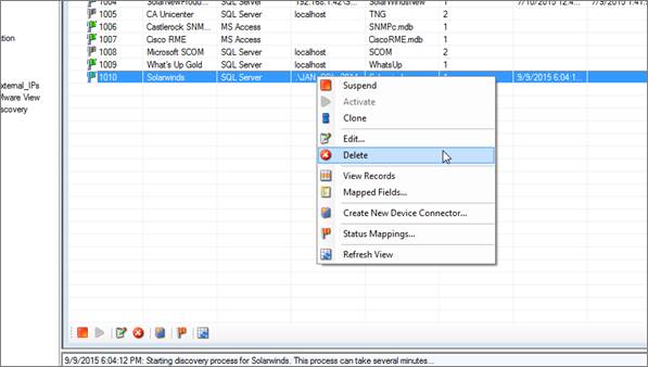
Deleting a device connector
Just like with built-in connectors, this action cannot be undone. It will remove all traces of the device connector in the ITK, as well as any type mappings associated with it, but it won’t remove any devices from netTerrain itself.
Tip:
Instead of deleting built-in connectors, it is recommended to simply change their status to suspended. That way, when an automatic scheduler is set up, any suspended device connectors will not trigger synchronization operations. Later, the connector may be reused.
4.7 Cloning a connector
A quick way to create a connector is to take an existing one and clone it. This is especially useful when the new connector has similar characteristics to the cloned one.
To clone a connector simply right click on the base connector and click on the ‘Clone connector’ option.
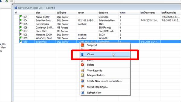
Cloning a connector
After cloning the connector, the new connector will have the same name as the cloned one. Proceed to change the name and any other parameters by editing the connector as usual.
5 Node connectors
Node connectors are hooks into external databases or files to import records and map them with netTerrain generic node objects. Connectors are a very useful resource to automate the process of creating documentation in netTerrain by taking advantage of existing data from your environment.
You can create any number of node connectors and each connector will be tied to a predefined node type in the netTerrain catalog. To create a node connector, you can utilize a wizard to connect to the data source and map table columns to custom fields in netTerrain.
All node connectors in the ITK are user created and they can be found in the node connector list. From the connector list you can manage settings and schedule automated discovery processes.
Most of the functions and features for node connectors are very similar to the ones used for device connectors.
5.1 Viewing node connectors
To see which node connectors are currently included in the ITK, simply go to View-> Node connector list (Ctrl-O) and a list view of all the node connectors will be displayed.
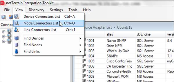
Node connector list view
5.2 Prerequisites for creating node connectors
To create a new node connector, netTerrain must know certain aspects of the data source, such as connection properties, the table or query to import the data from and the fields that will be mapped to custom fields in netTerrain.
5.2.1 Proxy or source database?
Just as with device connectors, the first step in creating a node connector requires knowing which database engine you will need to connect to.
The ITK can natively read data from SQL Server, Oracle, PostgreSQL, MySQL and MS Access (jet) databases. If the source data resides in one of those three engines, then the connection string is easy to create by simply filling out the appropriate login information in the node connector creator dialog.
In many cases though, the source information may be another database engine or a text file. In those situations, a node connector can still be created using a ‘proxy database’ (as explained earlier in this guide).
5.3 Step 1: creating the node connector
Similar to the device connector creation process, a 2-step wizard will guide you through the process of creating a node connector.
To start the node connector wizard, go to Tools-> Create New Node Connector. A similar button and a right click context menu are also available from the node connector list view.
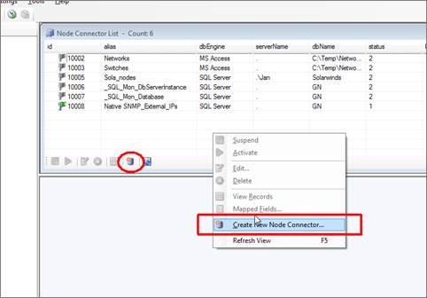
Creating a new node connector
5.3.1 Connection information tab
This tab stores the name and connectivity information, so that the ITK can properly read the data from the source.
5.3.1.1 Database engine
As mentioned before, Oracle, PostgreSQL, MySQL, SQL Server or MS Access databases are natively supported for direct connections between the ITK and the data source. Otherwise, you can use a proxy database (as explained in the previous chapter). For example, if you want to bring in records from a MySQL database, you can create linked tables in MS Access (or a linked server in SQL Server), which then (via queries) connect to the ITK.
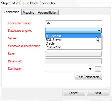
Connectivity tab showing the database engine drop down box
When using MS Access, the server is not required, as the path to the corresponding MS Access file will be used. In the case of SQL Server, the server and database name must be specified in the appropriate fields. With Oracle, a TNS name will typically need to be set up on the ITK machine.
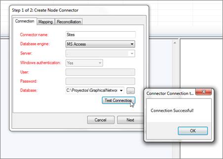
Setting up the connection tab for a node connector
5.3.1.2 Database credentials
Database credentials are only required for SQL Server, PostgreSQL, MySQL and Oracle-based node connectors. In both cases a user with read-only access to the source will suffice. Both Trusted connections and SQL Server authentication are supported for SQL Server-based node connectors.
5.3.1.3 Source Database
If the database engine is SQL Server, then the database field does provide a drop-down box of all the databases available for that server. For MS Access-based connectors use the ellipsis ‘..’ button to browse for the Access file (.accdb and .mdb extensions are supported). For Oracle-based connectors you must type in the TNS reference. For PostgreSQL-based connectors the Server field turns into a ‘DSN’ field. You must then make sure there is a DSN to the PostgreSQL database (from the machine hosting the ITK) and then reference that DSN in the DSN field.
5.3.2 Mapping tab
The mappings tab for custom connectors is essentially the same as for device connectors. The main difference is that device connectors need a device type mapping, whereas node connectors are explicitly mapped to one type. We’ll repeat the instructions specified in the previous chapters on how to fill out the mapping tab
5.3.2.1 Source table
The source table represents the table or view where the records that need to be pulled from the data source are stored.
Tip:
If you need to modify some of the data being imported into netTerrain or need to correlate more information that is available in other tables, create a view that “massages” that data for you and point the source table field to that view.
5.3.2.2 netTerrain Type
The type field for nodes is used to specify which node type from the netTerrain catalog is mapped to our source table. What this means is that once the ITK starts importing records through this node connector, every record will be an instance of the netTerrain type. Do not confuse this type field with the type field for device connectors (see chapters 3 and 4).
5.3.2.3 Default diagram
When importing nodes from a third-party data source, netTerrain can assign a default diagram for the node. This is especially important when the source table has no fields that can provide information about the parent diagram containing each node. This default diagram in netTerrain will serve as the initial repository for newly imported nodes. You can assign different diagrams for different node connectors instead of searching for nodes from multiple node connectors in one generic diagram. To specify a default diagram, at least one diagram needs to exist in netTerrain beforehand.
5.3.2.4 Parent locator field
An alternative to using a default diagram is to automatically place nodes under a specific parent object. This is possible if the source table contains a field that stores that parent ancestry data. This can be specified in the parent locator field.
Naturally, for the automatic placement to work, the parent diagrams must exist in netTerrain prior to importing nodes. It is possible to create a separate connector that pulls the parent objects in advance, which will then guarantee that the nodes will be placed under the corresponding parent objects.
5.3.2.5 Name field
The name field should contain the name or unique identifier for each node and it will be mapped to the name field in netTerrain. Technically, it is not necessary for this field to pull values that are unique, but it is highly recommended. If the name field is mapped to a field in the source table that does contain repeated values, then any nodes with the same name field value will throw an error during the update process. Also, if nodes names are not unique in netTerrain, then if you decide to also import links using the ITK, any links that have repeated endpoints will not be imported.
5.3.2.6 X and Y coordinate fields
Coordinates can be used to automatically place nodes on a given diagram. These fields can be used to import positioning information from the source data. Positioning information can refer to latitude and longitude information or any custom coordinate system, such as a grid. This requires the netTerrain parent object to have a background with embedded coordinates. To configure coordinates in the ITK you must follow these steps:
- The parent object type must include a background image with embedded coordinates (see netTerrain User Guide).
- The source table must contain two coordinate fields (such as x and y or latitude and longitude).
- The coordinates for each record in the source data must fall within the boundaries defined for the background coordinate in netTerrain.
If no coordinate information is available, use the
5.3.2.7 WHERE clause
The last field of the second tab contains a WHERE clause. This can be used as a mechanism to filter certain records from the source table. The syntax of the WHERE clause must correspond to the flavor of SQL that the source database uses and must start with the ‘WHERE’ keyword (see the screenshot for an example).
Attention!
If the syntax in a WHERE field is incorrect, the discovery process will fail. When writing the clause, you must start the filter with the ‘WHERE’ keyword itself (for example ‘WHERE location=1’). Also, mind that SQL syntax as it may differ from different database engines. SQL Server uses T-SQL, Oracle uses PL/SQL and PostgreSQL, MySQL and MS Access also have slightly different flavors of SQL so there may be minor differences in the syntax. If you want to avoid all this hassle don’t use the WHERE clause and instead connect to a custom view where the information is already pre-filtered.
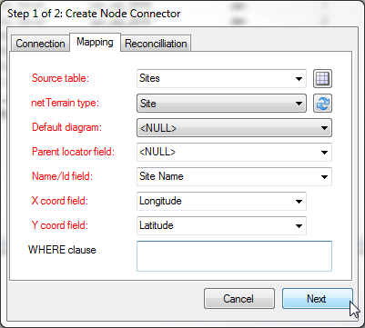
Configuring the mapping tab
5.3.3 Reconciliation
The last tab deals with the mechanism for node reconciliation into netTerrain.
5.3.3.1 Updating existing nodes in netTerrain
If you want to update any field changes for nodes that exist in the data source and have already been imported into netTerrain during a previous cycle, then the ‘Update existing nodes’ combo box needs to be set to ‘Yes’.
5.3.3.2 Inserting new nodes into netTerrain
New nodes that do not exist in netTerrain and were discovered by the node connector will be inserted into netTerrain, if the following criteria apply:
- A default diagram or a parent locator field has been assigned for the node connector.
- The ‘Insert new nodes’ combo box is set to ‘Yes’.
5.3.3.3 Deleting nodes without matches
Nodes that exist in netTerrain and were tagged as imported by the node connector during a previous cycle and do no longer exist may be:
- Deleted from netTerrain by setting the ‘Delete nodes without matches’ combo box to ‘Yes’.
- Kept in netTerrain by setting the combo box to ‘No’.
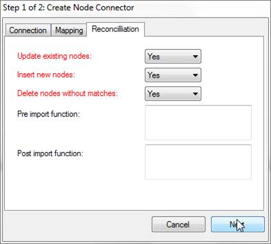
Reconciliation tab
5.3.3.4 Pre and post import functions
These fields are used to place advanced functions that are processed before and after an import occurs. An example of a pre-import function could be a call to execute a stored procedure in the source data, which massages the records to be imported. An example of a post import function could be a layout algorithm that is triggered after the import to automate node positioning.
Attention!
The Pre and Post import function fields are currently reserved for Graphical Networks consultants. If you think you need a function to perform a specific action, please enter a ticket in the support portal.
5.4 Step 2: Mapping custom fields
Now that we have set the main parameters for the node connector, we can proceed to map fields from the source with custom fields in netTerrain. This is done in step 2 of our wizard. This step works pretty much the exact same way as we have seen before, but we’ll review it again here.
5.4.1.1 Mapping fields when they already exist in netTerrain
When the destination fields in netTerrain already exist, you can simply map fields one by one or also use the option to map all fields with matching names.
To map a field from the source to an existing field in netTerrain, simply choose it from the source table and then select the corresponding destination field in netTerrain that you want the source field mapped to. Finally click on ‘Map Selected Fields’ and you are done.
Once added, the new mapping will show up in the ‘Fields currently mapped’ list view.
To remove a mapping, simply select it and hit ‘Remove’.
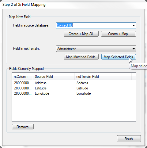
Adding a new mapped field
When many of the fields in the source match the names of the fields in netTerrain, you can map them all in one simple process by clicking on the ‘Map Matched Fields’ button.
5.4.1.2 Mapping fields when they don’t exist in netTerrain
As mentioned before, in case one or more of the source fields do not yet exist for the type in netTerrain, you can map and create them in the catalog, at once, straight from the ITK.
To map and create just one field from the source, select it first from the drop-down list, and then click on ‘Create + Map’ button. If you want to Create and map all the fields in the source, click on the ‘Create + Map All’ button.
Any mappings can be removed from this dialog by selecting the mapping from the list view and clicking on the remove button.
Attention!
When using x and y (or lat / long) coordinates you must also map the corresponding netTerrain fields in this step as well.
5.5 Next steps
Once the ‘Finish’ button is clicked, the node connector should be registered in the ITK database and force an application restart. The application restart is necessary so that the new connector can be registered in the ITK UI menus and list views.
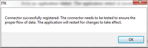
After the restart, the new node connector will be available in the node connector list and any applicable menu options.
Even if a node connector is successfully registered, the actual import process may fail. Some factors that could affect the proper functioning of a node connector include:
- Certain key fields may have been deleted from type definition in netTerrain.
- NULL values in names or parent mapping fields.
- Syntax errors in a WHERE clause.
It is highly recommended to test the node connector by first running a discovery and then a preview of the reconciliation process.
Just as with device connectors, you can edit a node connector afterwards. Consider that editing a node connector may trigger a drop and create process of the node table, which will require a full discovery of the source data.
If later on you need to make changes to the mapped fields, these are also managed the same way as with device connectors.
5.6 Discovering and reconciling nodes
The discovery process for node connectors involves reading the source data and dumping it into a raw table in the ITK. This is the first (of two) steps to synchronize the source data with netTerrain (both processes can be automated when scheduling connectors).
These two processes are executed in the same order and fashion as with devices connectors (see previous chapter).
To run a discovery for the first time simply go to the ‘Discovery’ menu and click on the appropriate node connector to discover data from.
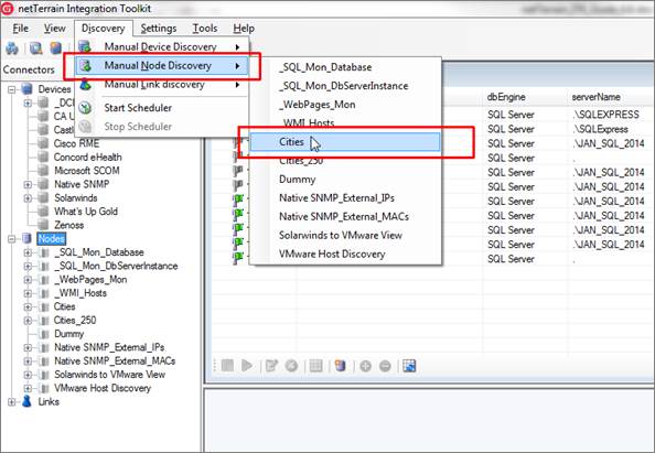
Initiating node connector discovery
Tip:
You can also start a discovery by double clicking on the connector entry and then clicking on the ‘Refresh List (Discover)’ button, as displayed below.
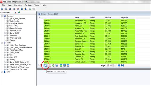
Running a discovery from the connector view
By clicking on this submenu, netTerrain will start the process of importing the raw data from the third-party data source and will display the results under the corresponding view menu. Note that the nodes are not yet imported into netTerrain. The latter involves the execution of the reconciliation process. The output window will also show the start and end times of the discovery process.
5.6.1 Viewing the results
Once nodes have been imported as raw data into netTerrain, you can view these nodes and associated columns by clicking on the ‘View’ menu and the corresponding node connector, or by double clicking on the connector in the connector list.
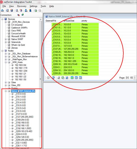
List of discovered nodes for a node connector
Each node will be represented by a row and will contain values for several columns that will depend on which fields were mapped during the node connector creation process.
Just like with devices, the list view uses specific color codes to identify the reconciliation status of the node in netTerrain.
Nodes can also be viewed from the tree view. In addition, if a user wants to view a node in more detail, by double-clicking on the row entry the ITK will display a dialog box with each attribute for the node.
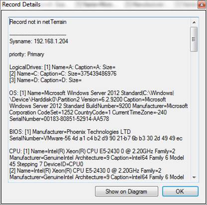
Node details
5.7 Node reconciliation
So far, the discovery has simply pulled the data from the source into a raw table in the ITK, but it is not yet in netTerrain. To import nodes into netTerrain, we need to reconcile the discovered items with the netTerrain database. This reconciliation process includes the insert, update and/or delete of nodes from the data source into netTerrain, according to the rules specified in the node connector mapping settings.
5.8 Deleting and suspending node connectors
Node Connectors are deleted from the ITK by following these steps:
- Open the appropriate connector list (Ctrl-O).
- Click on the connector to be deleted.
- Click on the delete button (or right-click->delete connector).
Attention!
Note that this action cannot be undone. It will remove all traces of the connector from the ITK, but it will not remove objects in netTerrain.
Connectors can also be suspended, instead of deleted. That way, when an automatic scheduler is set up, any suspended connectors will not start the discovery and reconciliation process. To suspend a connector, right click on it from the list and click on the ‘Suspend’ option.
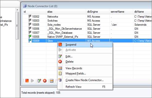
Suspending a connector
6 Link Connectors
Link connectors are hooks into external databases or files to import records and map them with netTerrain link objects. Link connectors are a very useful resource to automate the process of creating documentation in netTerrain by taking advantage of existing data from your environment.
You can create any number of link connectors and each one will be tied to a predefined link type in the netTerrain catalog. To create a link connector, you can utilize a wizard to connect to the data source and map table columns to custom fields in netTerrain.
All link connectors in the ITK are user created and they can be found in the link connector list. From the connector list you can manage settings and schedule automated discovery processes.
6.1 Viewing link connectors
To see which link connectors are currently included in the ITK, simply go to View-> Link connector list (Ctrl-K) and a list view of all the link connectors will be displayed.
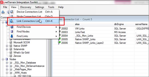
Link connector list view
6.2 Step 1: creating the link connector
Just like with device and node connectors, to create a new link connector, netTerrain must know certain aspects of the data source, such as connection properties, the table or query to import the data from and the fields that will be mapped to custom fields in netTerrain. You also need to determine whether the data source is natively supported or not, in which case you may want to set up a proxy database (see previous chapters on setting up a proxy database).
Also, similar to the node connector creation process, a 2-step wizard will guide you through the process of creating a link connector.
To start the link connector wizard, go to Tools-> Create New Link Connector. A similar button and a right click context menu are also available from the link connector list view.
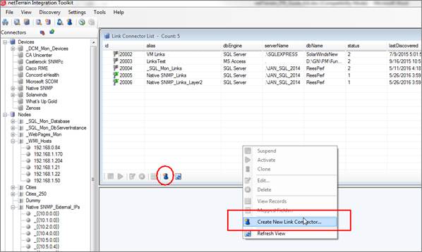
Creating a new link connector
6.2.1 Connection information tab
This tab stores the name and connectivity information, so that the ITK can properly read the data from the source.
6.2.1.1 Database engine
As mentioned before, Oracle, PostgreSQL, MySQL, SQL Server or MS Access databases are natively supported for direct connections between the ITK and the data source. Otherwise, you can use a proxy database (as explained in the previous chapter). For example, if you want to bring in records from a MySQL database, you can create linked tables in MS Access (or a linked server in SQL Server), which then (via queries) connect to the ITK.
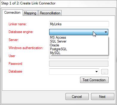
Connectivity tab showing the database engine drop down box
When using MS Access, the server is not required, as the path to the corresponding MS Access file will be used. In the case of SQL Server, the server and database name must be specified in the appropriate fields. With Oracle, a TNS name will typically need to be set up on the ITK machine.
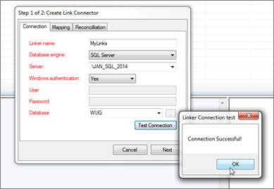
Setting up the connection tab for a link connector
6.2.1.2 Database credentials
Database credentials are only required for SQL Server, PostgreSQL, MySQL and Oracle-based link connectors. In both cases a user with read-only access to the source will suffice. Both Trusted connections and SQL Server authentication are supported for SQL Server-based link connectors.
6.2.1.3 Source Database
If the database engine is SQL Server, then the database field does provide a drop-down box of all the databases available for that server. For MS Access-based connectors use the ellipsis ‘..’ button to browse for the Access file (.accdb and .mdb extensions are supported). For Oracle-based connectors you must type in the TNS reference. For PostgreSQL-based connectors the Server field turns into a ‘DSN’ field. You must then make sure there is a DSN to the PostgreSQL database (from the machine hosting the ITK) and then reference that DSN in the DSN field.
6.2.2 Mapping tab
The mappings tab for custom connectors is essentially the same as for node connectors. The main two differences between a node and a link connector are the following:
1) Link connectors do not require a default or parent network for proper placing of records in netTerrain. Instead, they require two fields that identify the endpoints of each link.
2) Link connectors are automatically rendered based on the location of the endpoints, which means that no x/y or other auto positioning methods apply to links.
6.2.2.1 Source table
The source table represents the table or view where the records that need to be pulled from the data source are stored.
Tip:
If you need to modify some of the data being imported into netTerrain or need to correlate more information that is available in other tables, create a view that “massages” that data for you and point the source table field to that view.
6.2.2.2 netTerrain Type
The type field for links is used to specify which link type from the netTerrain catalog is mapped to our source table. What this means is that once the ITK starts importing records through this link connector, every record will be an instance of the netTerrain type. Do not confuse this type field with the type field for device connectors (see chapters 3 and 4).
6.2.2.3 Name field
The name field should contain the name or unique identifier for each link and it will be mapped to the name field in netTerrain. Technically, it is not necessary for this field to pull values that are unique, but it is highly recommended. If the name field is mapped to a field in the source table that does contain repeated values, then any links with the same name field value will throw an error during the update process.
6.2.2.4 Endpoint locator fields
As mentioned above, link connectors require two endpoint identifiers. These endpoints can consist of nodes, devices, ports or any other category in netTerrain. Moreover, the endpoints can be a concatenation of several nodes. Your source database will need to contain a field that identifies the starting point for the link and another one for the ending point.
6.2.2.5 Endpoint separator (and how to create connections between ports)
Link connectors can use concatenated values to create links in netTerrain. This is very useful when the final endpoint nodes do not have unique names (such as ports, that are typically just numbered). For instance, your endpoint fields may consist of a concatenation of ‘device::card::port’, which uniquely identifies the endpoints. It is important to note that you still must have the endpoint values in one field. You cannot concatenate values from multiple fields. If your source data does not contain a single field with the concatenated values, then you can construct that field yourself as a concatenation of the original fields in some intermediate query or table.
In order to successfully use concatenated values, you must specify the character that is used as a separator. The ITK, upon reconciling the data, will then parse the endpoints, look for the separator and work its way down in the hierarchy. For instance, let’s say a certain link has the a value of Cisco6009-primary::4::3 for endpoint 1, and we specify the string ‘::’ as the endpoint separator, then netTerrain will parse this value as follows:
-
The ITK will first look for a node in netTerrain called ‘Cisco6009-primary’. This node needs to have a unique name
-
If the ITK determines that the node is a device, and there is more than one part remaining, it will then look for a card (in this case called ‘4’)
-
When the ITK gets to the last part, it determines it must be a port (in this case ‘3’) and creates the link
6.2.2.6 WHERE clause
The last field of the second tab contains a WHERE clause. This can be used as a mechanism to filter certain records from the source table. The syntax of the WHERE clause must correspond to the flavor of SQL that the source database uses and must start with the ‘WHERE’ keyword (see the screenshot for an example).
Attention!
If the syntax in a WHERE field is incorrect, the discovery process will fail. When writing the clause, you must start the filter with the ‘WHERE’ keyword itself (for example ‘WHERE location=1’). Also, mind that SQL syntax as it may differ from different database engines. SQL Server uses T-SQL, Oracle uses PL/SQL and PostgreSQL, MySQL and MS Access also have slightly different flavors of SQL so there may be minor differences in the syntax. If you want to avoid all this hassle don’t use the WHERE clause and instead connect to a custom view where the information is already pre-filtered.
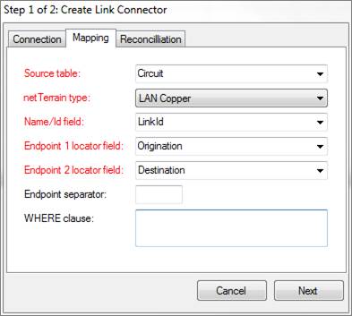
Configuring the mapping tab for a link connector
6.2.3 Reconciliation
The last tab deals with the mechanism for link reconciliation into netTerrain.
6.2.3.1 Updating existing links in netTerrain
If you want to update any field changes for links that exist in the data source and have already been imported into netTerrain during a previous cycle, then the ‘Update existing links’ combo box needs to be set to ‘Yes’.
6.2.3.2 Inserting new links into netTerrain
New links that do not exist in netTerrain and were discovered by the link connector will be inserted into netTerrain, if the following criteria apply:
- The endpoint fields have been assigned for the link connector.
- The ‘Insert new links’ combo box is set to ‘Yes’.
6.2.3.3 Deleting links without matches
Links that exist in netTerrain and were tagged as imported by the link connector during a previous cycle and do no longer exist may be:
- Deleted from netTerrain by setting the ‘Delete links without matches’ combo box to ‘Yes’.
- Kept in netTerrain by setting the combo box to ‘No’.
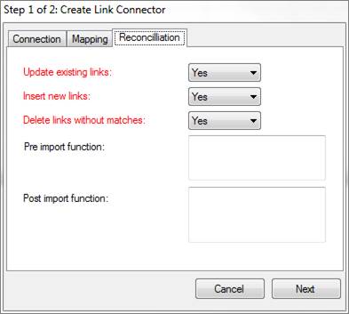
Reconciliation tab
6.2.3.4 Pre and post import functions
These fields are used to place advanced functions that are processed before and after an import occurs. An example of a pre-import function could be a call to execute a stored procedure in the source data, which massages the records to be imported.
Attention!
The Pre and Post import function fields are currently reserved for Graphical Networks consultants. If you think you need a function to perform a specific action, please enter a ticket in the support portal.
6.3 Step 2: Mapping custom fields
Now that we have set the main parameters for the link connector, we can proceed to map fields from the source with custom fields in netTerrain. This is done in step 2 of our wizard and is very similar to how you map custom fields for connectors or devices (as seen before).
6.3.1.1 Mapping fields when they already exist in netTerrain
When the destination fields in netTerrain already exist, you can simply map fields one by one or also use the option to map all fields with matching names.
To map a field from the source to an existing field in netTerrain, simply choose it from the source table and then select the corresponding destination field in netTerrain that you want the source field mapped to. Finally click on ‘Map Selected Fields’ and you are done.
Notice that the fields do not have to have the same names.
Once added, the new mapping will show up in the ‘Fields currently mapped’ list view.
To remove a mapping, simply select it and hit ‘Remove’.
When many of the fields in the source match the names of the fields in netTerrain, you can map them all in one simple process by clicking on the ‘Map Matched Fields’ button.
6.3.1.2 Mapping fields when they don’t exist in netTerrain
As mentioned before, in case one or more of the source fields do not yet exist for the type in netTerrain, you can map and create them in the catalog, at once, straight from the ITK.
To map and create just one field from the source, select it first from the drop-down list, and then click on ‘Create + Map’ button. If you want to Create and map all the fields in the source, click on the ‘Create + Map All’ button.
6.4 Next steps
Once the ‘Finish’ button is clicked, the link connector should be registered in the ITK database and force an application restart. The application restart is necessary so that the new connector can be registered in the ITK UI menus and list views.
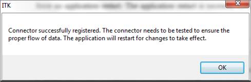
After the restart, the new link connector will be available in the link connector list and any applicable menu options.
Even if a link connector is successfully registered, the actual import process may fail. Some factors that could affect the proper functioning of a link connector include:
- Certain key fields may have been deleted from type definition in netTerrain.
- NULL values in names or endpoint mapping fields.
- Syntax errors in a WHERE clause.
It is highly recommended to test the link connector by first running a discovery and then a preview of the reconciliation process.
Just as with node connectors, you can edit a link connector afterwards. Consider that editing a link connector may trigger a drop and create process of the link table, which will require a full discovery of the source data.
If later you need to make changes to the mapped fields, these are also managed the same way as with node connectors.
6.5 Discovering and reconciling links
The discovery process for link connectors involves reading the source data and dumping it into a raw table in the ITK. This is the first (of two) steps to synchronize the source data with netTerrain (both processes can be automated when scheduling connectors).
These two processes are executed in the same order and fashion as with devices connectors (see chapter 4).
The ITK automatically takes care of properly connecting a link with its endpoints. The following important rules for links apply:
- Links must have two endpoints and these endpoints need to exist prior to the reconciliation process for a link record to be created.
- Any link that has one or more endpoints that appear to be repeated in netTerrain (i.e. the endpoint name is not unique) will not be imported and an error will be logged.
- If both endpoints of a given link exist on different diagrams, netTerrain automatically creates an inter diagram link and takes care of the creation of reference nodes.
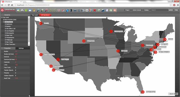
Example of nodes and links discovered from the ITK
6.6 Deleting and suspending link connectors
Link Connectors are deleted from the ITK by following these steps:
- Open the appropriate connector list (Ctrl-L).
- Click on the connector to be deleted.
- Click on the delete button (or right-click->delete connector).
Attention!
Note that this action cannot be undone. It will remove all traces of the connector from the ITK, but it will not remove objects in netTerrain.
Connectors can also be suspended, instead of deleted. That way, when an automatic scheduler is set up, any suspended connectors will not start the discovery and reconciliation process. To suspend a connector, right click on it from the list and click on the ‘Suspend’ option.

Suspending a link connector
7 Monitoring
In the previous chapters we saw powerful features for importing data from external data sources using device, node and link connectors. In addition to the discovery of data from external databases, the ITK also has several native monitoring tools:
-
An SNMP auto-discovery engine
-
A WMI discovery engine
-
An AWS discovery utility
-
An environmental monitoring module supporting IPMI, SNMP, SSH, WS-MAN, HTTPS and Inband Protocol (separate license required, please consult the Environmental Monitoring module guide for details)
-
A simple website monitoring tool
-
A SQL Server monitor
7.1 General parameters
The monitoring engine for the ITK includes a series of configuration settings that help you tune the process to your liking. The configuration options include some general parameters that, such as threads, fields and more which you can access by clicking on Settings->Monitoring->Configuration (or ctrl-g).
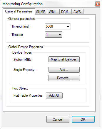
Configuration options for monitoring
The general parameters for SNMP discovery include the timeout and multithreading settings, MIB properties (which let you add properties to devices in netTerrain besides just SNMP), and settings for the port object.
7.1.1 Timeout and threads
The timeout setting controls the time for a background worker process to wait for a device to respond to an SNMP get command. The multithreading combo box option provides a few values for the number of threads that the engine uses for all discovery purposes. The default number of threads is 2. For any value greater than 1, the engine issues multiple parallel threads to discover the network faster. We do not recommend using more than 5 threads, other than for testing purposes.
In general, we recommend using the default values for these general parameters, as they should suit most needs.
7.1.2 Device properties
The discovered properties won’t be very useful if the corresponding fields are not created in the netTerrain catalog for each corresponding type. For example, the ITK may be able to discover ifSpeed for ports, but if the port object in the netTerrain catalog doesn’t include that field, then it won’t be reflected in the project either. The same applies for devices: if, say, the sysDescription field does not exist in the netTerrain catalog, then the discovered sysDescription values for any devices that the ITK scans will not be reflected in the netTerrain diagrams.
For convenience, the ITK includes buttons that create these fields automatically, without having to go to the netTerrain catalog. This is particularly useful for devices, since a given system MIB value (the MIBs mapped to devices) would have to be created for any possible type that we expect to be discovered via SNMP. This could be a tedious task involving dozens or hundreds (maybe thousands) of types.
The process for creating new values for all device types in the catalog was explained in chapter 3 (Mapped fields missing in netTerrain), but we’ll repeat it here for convenience.
To set up a specific netTerrain property for devices, click on the ‘Add...’ button in the Global Device Properties group. This will prompt you to enter the name of the property you want created in the catalog for devices.
The ITK is smart enough to only add the field to the types that are missing it. And yes, be patient indeed, this process can take a couple of minutes.
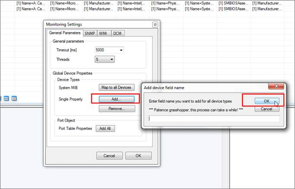
Adding a field to all device types in netTerrain
You can also remove a field for all device types using the ‘Remove...’ button.
You can also add all System MIB properties at once, by clicking on the ‘Map to all Devices’ button and have patience, as this process can take several minutes to execute.
For ports, there is a button that simply adds to the port object type every interface group MIB property described at the beginning of this chapter.
Attention!
Be careful with these functions as they affect all types and instances in netTerrain! Also remember that the properties will be created for every single device type in netTerrain!
7.2 SNMP auto-discovery
The Native SNMP auto-discovery module can discover devices from the network, by polling the device management IP addresses. It will then discover properties from those devices using a predefined list of so-called ‘MIB’ (Management Information Base) variables. This component currently supports versions SNMPv1, SNMPv2c and SNMPv3.
Via SNMP, the ITK can discover the following device related information:
-
Standard System MIB properties
-
Any custom (public or private) MIB, which can be mapped to any custom field in netTerrain
-
Interface information, including status, reading from the MIB interface table
-
Layer 3 links (via IP address and routing tables)
-
Layer 2 links (via interface and bridge tables)
-
Up/down status for devices (this also uses Ping as a primary method, along with SNMP System get as a backup method)
Once devices are discovered, this module behaves much like a device connector in the sense that it maps the discovered elements with devices in netTerrain. Moreover, the ITK also uses a pre-defined device connector specifically for native SNMP. This predefined connector is part of the device connector list and is called ‘Native SNMP’ (with the id 1001). This connector can also be scheduled for automatic discovery and reconciliation, just like any other connector.
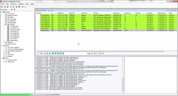
Native SNMP discovery list view
The Native SNMP discovery configuration for SNMP parameters as well as for the connector itself can be accessed from the Settings->Monitoring-> SNMP menu. We’ll review each submenu in a bit.
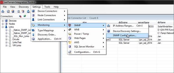
Native SNMP configuration menus and settings
7.2.1 Built-in MIBs
The foundation of an SNMP-based management system is a database containing information about the objects in the network to be queried. This database is referred to as the Management Information Base (MIB) and each resource to be managed in that database is an object. The MIB then is a structured collection of objects in the form of a tree. Associated with each object in the tree is an object identifier (OID) which follows a notation (Abstract Syntax Notation 1 or ASN.1) consisting of a set of integers separated by dots. The figure below illustrates part of the MIB-2 structure.
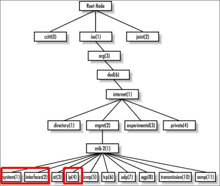
MIB-2 structure
The Native SNMP discovery uses the following OID prefixes (leafs depicted in red above):
-
System group (OID 1.3.6.1.2.1.1): they obtain basic device information.
-
Interface group (OID 1.3.6.1.2.1.2): they obtain basic interface (port) information. This data can be automatically mapped to the ports defined for a given type in the netTerrain catalog.
-
IP address group (OID 1.3.6.1.2.1.4): they comprise the IP address and routing table MIBs to obtain layer 3 link information between devices.
7.2.1.1 System MIBs
The system MIBs that are currently supported include the list below (we also include the ASN.1 definition for each):
-
sysName: “An administratively-assigned name for this managed node. By convention, this is the node's fully-qualified domain name”.
-
ipAddress
-
sysObjectId: “The vendor's authoritative identification of the network management subsystem contained in the entity. This value is allocated within the SMI enterprises subtree (1.3.6.1.4.1) and provides an easy and unambiguous means for determining `what kind of box' is being managed”.
-
sysUpTime: “The time (in hundredths of a second) since the network management portion of the system was last re-initialized”.
-
sysContact: “The textual identification of the contact person for this managed node, together with information on how to contact this person”.
-
sysDescr: “A textual description of the entity. This value should include the full name and version identification of the system's hardware type, software operating-system, and networking software. It is mandatory that this only contain printable ASCII characters”.
-
sysLocation: “The physical location of this node”.
-
sysServices: “The value which indicates the set of services that this entity primarily offers. The value is a sum. This sum initially takes the value zero, Then, for each layer, L, in the range 1 through 7, that this node performs transactions for, 2 raised to (L - 1) is added to the sum. For example, a node which performs primarily routing functions would have a value of 4 (2^(3-1)). In contrast, a node which is a host offering application services would have a value of 72 (2^(4-1) + 2^(7-1))”.
-
ifNumber: “The number of network interfaces (regardless of their current state) present on this system”.
In addition, devices will have a lastDiscovered timestamp appended to them, which is determined by the ITK itself.
7.2.1.2 Interface MIBs
When port monitoring is enabled, the ITK can discover interface properties for devices using the interfaces group MIB (not yet supported with SNMPv3). The properties that can be monitored include:
-
ifDescr: “Textual string containing information about the interface. This string should include the name of the manufacturer, the product name and the version of the hardware interface”.
-
ifType: “The type of interface, distinguished according to the physical/link protocol(s) immediately `below' the network layer in the protocol stack”.
-
ifSpeed: “An estimate of the interface's current bandwidth in bits per second. For interfaces which do not vary in bandwidth or for those where no accurate estimation can be made, this object should contain the nominal bandwidth”.
-
ifPhysAddress: “The interface's address at the protocol layer immediately `below' the network layer in the protocol stack. For interfaces which do not have such an address (e.g., a serial line), this object should contain an octet string of zero length.
-
ifAdminStatus: “The desired state of the interface”.
-
ifOperStatus: “The current operational state of the interface”.
-
ifLastChange: “The value of sysUpTime at the time the interface entered its current operational state. If the current state was entered prior to the last re-initialization of the local network management subsystem, then this object contains a zero value”.
Of special interest are the ifAdminStatus and ifOperStatus, which can be used to represent status values in netTerrain and be used as a visual override to change the port colors. Possible values for these parameters are:
-
up (1)
-
down (2)
-
testing (3)
7.2.1.3 IP address table and routing table MIBs
When link monitoring is enabled, the ITK can discover layer-3 topology for routers or devices that store routing table information in the IP group MIBs (not yet supported with SNMPv3).
Discovered links will include the following properties:
- ipRouteDest: “The destination IP address of this route. An entry with a value of 0.0.0.0 is considered a default route. Multiple routes to a single destination can appear in the table, but access to such multiple entries is dependent on the table-access mechanisms defined by the network management protocol in use”.
- ipRouteAge: “The number of seconds since this route was last updated or otherwise determined to be correct”.
- ipRouteMask: “Indicate the mask to be logical-ANDed with the destination address before being compared to the value in the ipRouteDest field”.
- ipRouteIfIndex: “Index value which uniquely identifies the local interface through which the next hop of this route should be reached. The interface identified by a particular value of this index is the same interface as identified by the same value of ifIndex”.
- ipRouteMetric1: “Primary routing metric for this route. The semantics of this metric are determined by the routing-protocol specified in the route's ipRouteProto value. If this metric is not used, its value should be set to -1”.
- ipRouteNextHop: “IP address of the next hop of this route”.
- ipRouteType: “Type of route”.
- ipRouteProto: “Routing mechanism via which this route was learned”.
The ipRouteType is an integer value with the following translation table:
-
1: other
-
2: invalid
-
3: direct
-
4: indirect
The ITK will store the actual integer value for each route and append the string value when it reconciles the routes as links in netTerrain.
The ipRouteProto is an integer value with the following translation table:
-
1: other
-
2: local
-
3: netmgmt
-
4: icmp
-
5: egp
-
6: ggp
-
7: hello
-
8: rip
-
9: is-is
-
10: es-is
-
11: ciscoIgrp
-
12: bbnSpflgp
-
13: ospf
-
14: bgp
The ITK will store the actual integer value for each route ipRouteProto and append the string value when it reconciles the routes as links in netTerrain.
7.2.2 Configuring SNMP parameters
The first step in configuring the Native SNMP discovery engine is to set up some basic parameters. To access the SNMP configuration, go to Settings->Monitoring-> SNMP-> Configuration (or ctrl-G -> SNMP tab).
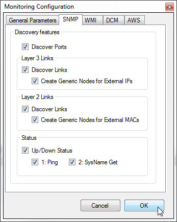
SNMP configuration
The SNMP discovery features control the granularity of the information you will be retrieving from the network.
When the ‘Discover Ports’ option is checked, the ITK will scan all interfaces associated with a discovered device. In the next section we will review how we can control which properties can be scanned for a specific IP address or range.
When the ‘Discover Links’ for Layer 3 option is checked, the ITK will scan IP address tables and routing tables for the managed device to determine what routes were configured for that particular device. netTerrain will then display these routes as links between that device and the endpoints.
In addition, when this option is checked, the ‘Create generic nodes for external IPs’ will be enabled. If this is also checked, netTerrain will automatically create generic nodes for any IP addresses that exist in the routing tables, which are not part of the registered IP address (i.e. not directly discoverable via SNMP).
When the ‘Discover Links’ for Layer 2 option is checked, the ITK will scan the MAC address tables and bridging tables for the managed device to determine what layer 2 links were configured for that particular device. netTerrain will then display these links as lines between that device and the endpoints.
In addition, when this option is checked, the ‘Create generic nodes for external MACs’ will be enabled. If this is also checked, netTerrain will automatically create generic nodes for any MAC addresses that exist in the bridging tables, which are not part of the registered MAC address tables of any discovered device (i.e. not directly discoverable via SNMP).
Finally, the status group lets you set up the real time status monitoring option for devices. When the ‘Up/down status’ option is checked, the ITK will update the status of an existing device using two methods:
-
Ping
-
SNMP device name get
We will review the live status options later in this chapter.
7.2.3 SNMP device connector settings
In many ways, the Native SNMP discovery behaves like any other device connector, with the difference being that the source is the SNMP discovery process itself and the connector has been built in advance.
Most of the parameters in the Native SNMP connector settings are not editable, but still, you can edit some of the connector settings to better suit your discovery needs. To open the SNMP connector settings, go to Settings->Monitoring->SNMP->Device Discovery Settings...
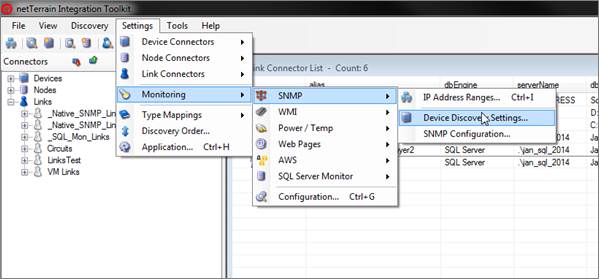
SNMP Connector settings
The editable parameters include:
-
Default diagram to place newly discovered objects.
-
Parent locator field (only sysLocation and sysContact can be used here).
-
All reconciliation tab parameters.
7.2.4 Configuring SNMP: IP address manager
To discover network devices using the Native SNMP we need to specify which individual IP addresses should be scanned and the parameters and discovery settings associated with each. This is done through the IP address manager tool.
Start by clicking on Settings->Monitoring-> SNMP->IP Address Ranges (or Ctrl-I) to open the IP address manager dialog.
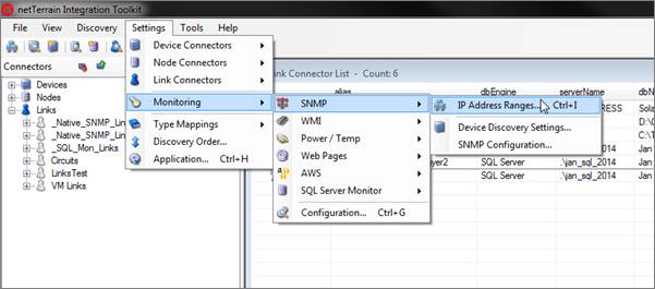
Setting up IP address ranges
The IP address ranges window will provide the user with an entry form for adding any number of Class-C IP address ranges or individual IP addresses (essentially with a range of 1 address).
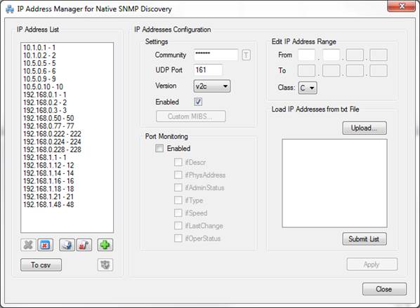
IP address manager dialog
IP addresses can be entered manually from the top right section of the dialog or they can be uploaded from a text file using the ‘Upload’ button.
7.2.4.1 Manual IP address entry
When you enter an IP address range manually, the manager will enable or disable each octet based on the entered values. The manager also checks for addressing consistency, thus avoiding malformed addresses. Once each octet in the ‘From’ and ‘To’ row has been entered you can click on the ‘Submit’ button to save the address. The settings and port monitoring that apply to the address are controlled in the middle sections of the dialog. These settings include:
- Community string: the default value is public and with the ‘T’ / ‘*’ button you can view the string in clear text or with password characters.
- Port: the UDP port number the SNMP agent listens to (the default is 161).
- SNMP version, which can be v1, v2c or v3.
- Enabled status: determines whether that address or range is enabled for discovery.
- Port monitoring enabled status: determines whether port monitoring is enabled for that address or range.
- Port monitoring MIBs: determines which MIBs should be discovered for that IP address or range.
Attention!
All IP addresses in the same range will share the same community string and port. If for a given range two or more IP addresses must use different settings, you must create two or more ranges.
7.2.4.2 Setting devices with SNMPv3
For devices that need to be discovered with SNMPv3, follow these simple steps:
1) First select that version from the drop-down box
2) Notice a key button appearing next to the version box
3) After clicking on that key button, fill out the SNMPv3 security credentials for that particular IP address range
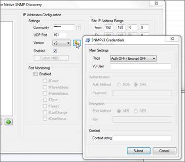
SNMPv3 security credentials form
SNMP version 3 provides additional security features compared to SNMPv1 and v2s, which only provide a community string parameter:
- A user identifier
- Authentication of the user who sent the PDU. The authentication protocols include SHA and MD5.
- Encryption of protocol data units (PDUs) to prevent unauthorized users from viewing the contents. SNMPv3 supports AES and DES for encryption.
- A context string parameter
As with SNMPv1 and v2c, each IP address or range can have its own SNMPv3 parameters.
Depending on the security settings for the range in question, you can set the flags that define which security features are needed.
7.2.4.3 Uploading IP addresses from a text file
The IP address manager tool has a utility to upload IP addresses straight from a text file. First, check the text file to make sure that there is one IP address per line. If any IP address is malformed or falls outside the range of a valid IP address it will not be loaded. Do not append or prepend any characters to the IP addresses, otherwise they will be discarded.
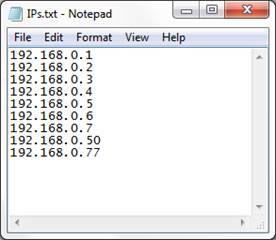
Sample IP address txt file
After you uploaded the IP addresses, the preview window will show which IP addresses were parsed correctly, as shown below:
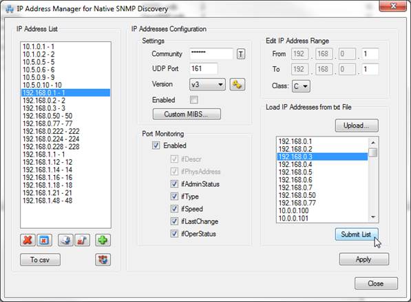
Parsed IP addresses from txt upload (bottom right)
Once you hit ‘Submit list’, the addresses will be loaded in the system using the IP address configuration settings in the middle section and displayed in the leftmost IP address list.
Attention!
All IP addresses in the parsed list (bottom right) will share the same community string and port defined in the settings. If for a given list two or more IP address should use different settings, you must add them in two or more upload steps, changing the settings in between.
Also, you cannot have two identical IP address ranges in the system, but it is possible to configure lists with overlapping IP addresses, which will cause redundant network scans.
7.2.4.4 Editing the settings of an IP address
To edit an IP address (or range) simply click on the entry on the IP address list and edit the settings in the middle section (community, UDP port, port settings, etc.). Note that to submit changes, you must then press on the ‘Apply’ button. As part of the editing process you can also change the address range itself.
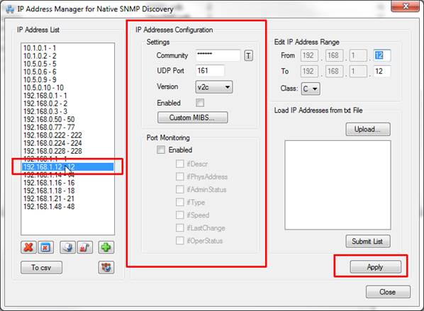
Editing an IP address (from left to right): select it, change the settings, and apply
7.2.4.5 Adding and removing addresses
To add a new IP address range, simply click on the ‘New’ button and this will clear the last octet values and port settings so that you can enter a new range. Of course, you can also add new IP addresses from a text file with the ‘Upload’ functionality.
r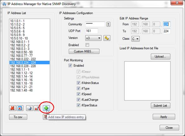
Adding a new IP address entry
To remove IP addresses simply select a range and click on the ‘Remove’ button. You can also remove all the IP addresses from the list, but be careful, as you cannot undo the removal process.
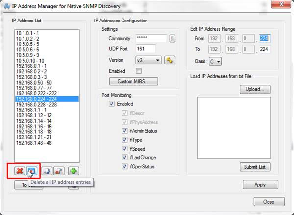
Deleting IP address entries
7.2.4.6 Enabling and disabling addresses
The IP address manager can enable or disable individual IP addresses or ranges. This comes in handy when you want to run a discovery against a smaller set of IP addresses without having to remove the remaining addresses from the list.
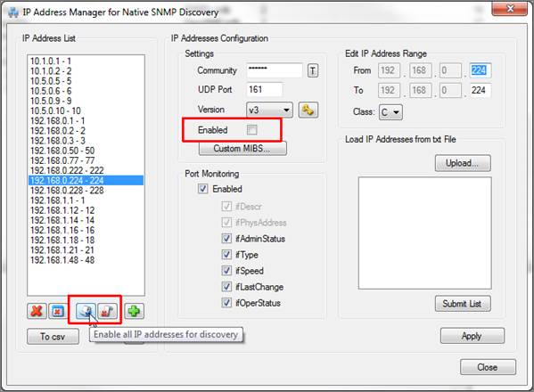
Enabling and disabling IP addresses from the discovery
7.2.4.7 Outputting a csv report of your IP addresses
The IP address manager has a very useful button to output a report of all the IP addresses. To launch the report, simply click on the ‘To csv’ button.

Output to csv
This report has a few interesting features:
- It shows every single IP address that was added to the list, not just the ranges themselves.
- It provides a column that shows the last time the ITK discovered a device with that IP address via Native SNMP. This can be useful when trying to determine IP addresses that do not exist on the network or cannot be reached via SNMP.
- It provides a summary of all IP addresses and unreachable IP addresses
Below is a sample csv report opened in Excel:
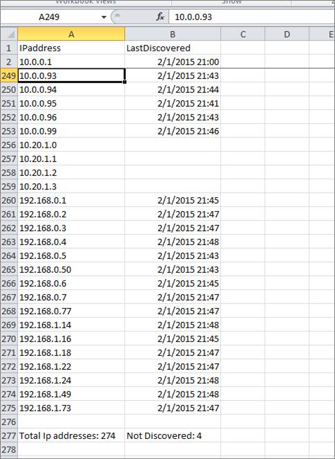
Sample csv IP address report
7.2.4.8 Running a ping sweep for an IP address range
One convenient way of finding out which devices could possibly exist on the network is to configure one or more IP address ranges and then running a ‘ping sweep’ for each range.
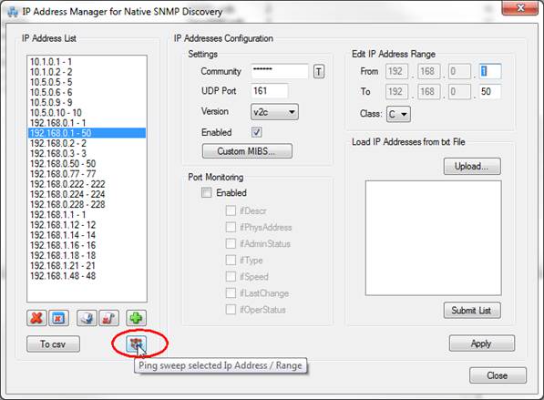
Running a ping sweep for an IP address range
A ping sweep basically executes a couple of pings against each IP address in that range and then stores the response in memory.
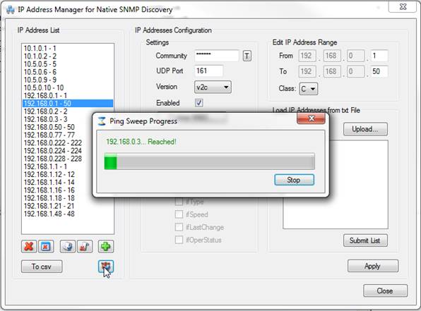
Ping sweep progress
Any address that can be pinged is labeled green; otherwise it is labeled in red.
After the range has been scanned, a csv report with the responses is generated by the ITK.
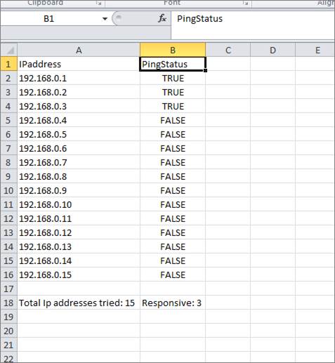
Ping sweep response
7.2.5 Mapping device types for native SNMP
As with other device connectors, the ITK uses a type field to match the source device type with the netTerrain catalog type. The native SNMP discovery connector uses the sysOID MIB for that purpose.
The ITK already has a wide list of supported sysOIDs in its database, but most of them are not mapped to a specific type in netTerrain. To filter the mappings for a specific OID, simply type it in the filter box and press ‘Enter’.
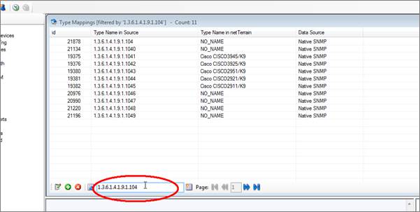
Using the filter text box to find a specific set of OIDs
To clear the filter, click on the ‘Clear filter’ button next to the text box.
To add a new mapping into the system, click on Settings->Type Mappings->New (or Ctrl-N). A type mapping needs to specify the Name of the type used in the source and the corresponding (exact) name used for the same type in netTerrain.
Attention!
Before adding a new mapping, make sure the OID does not already exist, by running it through the filter. If it exists and it is mapped to ‘NO NAME’, select the proper netTerrain model this OID should be mapped to (double click on the entry in the list view). In the mapping dialog, make sure the Data Source is ‘Native SNMP’.
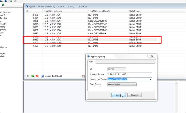
Native SNMP device mapping
Tip:
Before parsing over thousands of OIDs to see which ones are mapped, we recommend running a discovery first, and then configuring any unmapped types directly from the list of gray devices.
7.2.6 Starting the SNMP device discovery
To start the Native SNMP discovery, use the same procedure as with any other connector, by using the Discovery menu or directly from the Native SNMP list, using the discovery button.
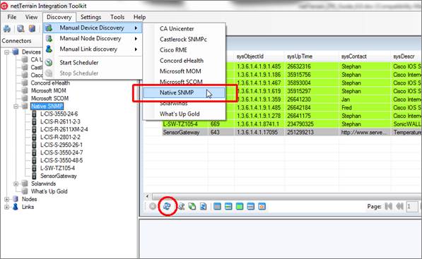
Starting the native SNMP discovery
Once started, the ITK will scan all the IP address ranges that were set up earlier. Note that as opposed to other discovery methods, this connector triggers a communication process with the actual devices and generates SNMP traffic on the network.
The performance of the scanning process depends on which parameters were set up for each IP address. Enabling the port discovery may increase the time spent on each device by an order of magnitude. Errors, such as non-responding hosts or OID problems due to mismatched SNMP versions will be shown in the output window. All SNMP activity is also logged.
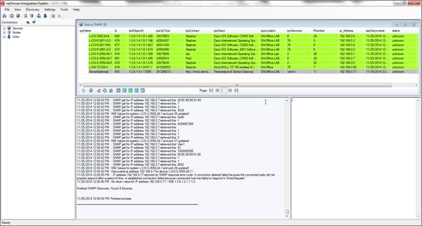
Running the Native SNMP discovery
Just like with other device connectors, the discovery has so far just pulled the data from the network into a raw table in the ITK, but it is not yet in netTerrain. From here on, the Native SNMP behaves pretty much like any other device connector. For convenience we will review the process in the upcoming sections.
To import devices into netTerrain, we need to reconcile the discovered items with the netTerrain database. This reconciliation process includes the insert, update and/or delete of devices from the discovered devices into netTerrain (depending on the rules specified in the Native SNMP connector mapping settings).
7.2.7 Viewing discovered device details
After the device discovery is completed, the Native SNMP list is populated with all the devices that were found on the network. The same color coding used for device connectors is utilized for the Native SNMP connector. Hence, each device can be in four possible states:
1) The same device also exists in netTerrain and it was discovered and reconciled into netTerrain by the Native SNMP connector. Such devices have a lime fill color, as shown below.
2) The same device also exists in netTerrain, but it was created manually or it was discovered and reconciled with netTerrain by a different connector. Such devices have a green fill color, as shown below.
3) The device in the connector table is currently not in netTerrain but the type has been mapped so that a reconciliation process (barring any parent issues) would create it in netTerrain. Such devices have a plain white fill color, as shown below.

4) The device in the connector table is currently not in netTerrain and the type has not been mapped, so a reconciliation process would create a generic device type in netTerrain (or yield an import error if the ‘Use generic devices for unmatched types’ application setting is unchecked). Such devices have a gray fill color, as shown below. Note that after a reconciliation process, any grey devices that do indeed trigger the creation of a generic device would now exist in netTerrain and displayed in lime.
Also, like the device connector cousins, the Native SNMP discovery provides a detailed view of each device when you double click on a specific entry in the Native SNMP device list.
7.2.8 Previewing a reconcilation process
Just like with regular device connectors, before importing and reconciling the data into netTerrain you should run a preview task. This will provide some insight into which devices will be inserted, updated or deleted. It will also provide a snapshot of devices that cannot be reconciled because no types have been mapped. The latter information can be used to add types to netTerrain or map existing netTerrain types with the device sysOID.
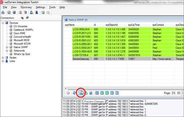
Previewing the reconciliation
The output window will display the expected operations and records affected by a reconciliation process.
The insert operations (the ‘Insert New Nodes’ option in the reconciliation section of the SNMP connector must be enabled) include:
- Records without a matching type in netTerrain: these are all the devices for which no source type information (make and model) has been matched with a type in netTerrain. In the event of a reconciliation, these records would skip the insert process.
- Records that are expected to be successfully inserted.
- Records with a missing parent in netTerrain: in case the SNMP connector uses a parent field to find the container diagram in netTerrain, any devices for which such parent cannot be matched with a diagram of the same name in netTerrain will also skip the insert process.
- Records with multiple parents in netTerrain: in case the SNMP connector uses a parent field to find the container diagram in netTerrain, any devices for which a parent value is matched with more than one diagram of the same name in netTerrain will skip the insert process. In other words, use unique names otherwise netTerrain doesn’t know which parent to choose from.
The update operations (the ‘Update Existing Nodes’ option in the reconciliation section of the SNMP connector must be enabled) include:
- Records to be updated: any records for which one or more field values have changed will be updated in netTerrain once reconciled. Notice that the output will display one entry for each field that has a change. For example, if a certain device has three changes in three fields, then the output will display three entries.
The delete operations (the ‘Delete Existing Nodes’ option in the reconciliation section of the SNMP connector must be enabled) include:
- Records to be deleted: any records that were inserted by that same connector in netTerrain in some previous operation, which are no longer in the source database will be deleted in the event of a reconciliation.
7.2.9 Reconciling SNMP devices with netTerrain
Once you are ready to reconcile the data into netTerrain you can start the process by simply opening the list view for the Native SNMP connector and clicking on the ‘reconcile’ button.
A button for triggering a discovery immediately followed by a reconciliation is also available (next to the reconcile button).
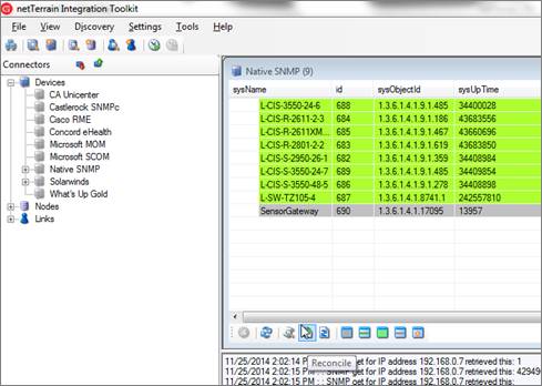
Reconciling data with netTerrain
Once the reconciliation starts, the ITK will display the same output displayed for the preview, with the actual devices being inserted, updated and /or deleted.
If port monitoring is enabled, then the ITK will also try to reconcile the ports discovered via SNMP with the port definitions that exist for the parent device type in the netTerrain catalog. For this to work correctly, port mappings need to exist for each device type. We will review this later in this chapter.
Attention!
Before adding a new mapping, make sure the OID does not exist, by running it through the filter. If it exists and it is mapped to ‘NO NAME’, select the proper netTerrain model this OID should be mapped to (double click on the entry in the list view). From the mapping dialog make sure the Data Source is set to ‘Native SNMP’.
7.2.10 Viewing ports
If the port discovery is enabled, a ‘Show ports’ context menu is available for any devices with discovered interfaces.
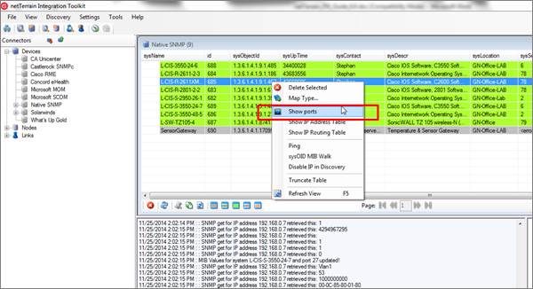
Show ports option
Any devices that have no discovered interfaces will have the ‘Show ports’ option disabled. When you click on the ‘Show ports’ menu a new list view will display all the ports associated with that particular device.
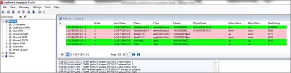
Port list
Ports displayed in green have an ifOperStatus value ‘up’, whereas the pink ones have a status value ‘down’.
Notice that the port list is really a filtered list, with the filter value being the parent device. You can clear the filter, which would then reload the view with all the interfaces for all devices discovered in the system. We recommend working with the filters, because you may have thousands of ports in the system, which would clutter the view. Now if you happen to be looking at an unfiltered view, you can see only ports belonging to a specific parent by right clicking on any port belonging to that parent device and selecting the ‘Filter by parent’ option.
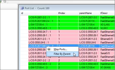
Filtering ports by parent
If you double click on a port, a detailed pop-up window with all port attributes will be displayed.
Attention!
The discovery process for ports may bring in a lot of undesired objects, such as NULL interfaces or VLANs. These objects may clutter the ITK interface but will not be imported into netTerrain unless they are somehow mapped with actual ports from the netTerrain catalog (see below).
7.2.11 Mapping port types
As mentioned before, if port monitoring is enabled, then every time a device reconciliation process occurs the ITK will also try to reconcile the ports discovered via SNMP with the port definitions that exist for the parent device type in the netTerrain catalog. For this to work correctly, port mappings need to exist for each device type.
Let’s try to understand this with an example. Imagine we discover a router with 4 ports on the motherboard. Usually the interface indexes (ifIndex) for ports are 1-based sequential integers. In our example, each port would be numbered from 1 through 4. But that same router may have its ports named eth1, eth2, eth3 and eth4 in the netTerrain catalog model. To correctly match each discovered port with its corresponding graphical representation in netTerrain we need to first set the “port mapping” for that device type.
The port mapping process is typically done before discovering anything, but it can be easier to first run a discovery and reconciliation process and then compare the MIB interface numbering with the device model generated in netTerrain. Once the mapping is done, we can rerun the reconciliation again. Just like with any other modeling or mapping process, this is a one-time task.
The port mapping can be accessed from a couple of different places. We can map the ports from the type mapping dialog, as displayed below:
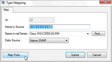
Accessing port mappings from the type mapping dialog
We can also access the port mapping by right clicking on any port that belongs to a certain device type.
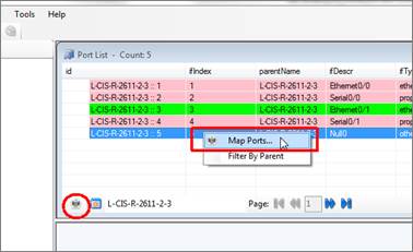
Accessing port mappings from the port view
The port mapping dialog displays a column with the ifIndex values per their MIB definition, another column with the port names in the mapped netTerrain device type and a list with the current mappings.
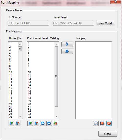
Port mapping dialog
The port mapping dialog has many ways to speed up the mapping process, but at its simplest:
- Select one or more ports from the left column.
- Select the same amount of ports from the right column.
- Click on the single arrow button and you are done.
As you map ports, the utilized ones are removed from the left and right columns, to avoid repeated mapped ports.
At this point it may become clear that the selected ports on the left and on the right are mapped in ascending order. The order that is used for the columns on the left or on the right can be reverted to descending. That way, the first selected port on the left is mapped to the last one on the right and so on. The right column has the following sorting features:
- Sort ports in ascending order.
- Sort ports in descending order.
- Sort ports by horizontal position on backplane (as visually modeled in the netTerrain catalog).
- Sort ports by vertical position on backplane (as visually modeled in the netTerrain catalog).
- reverse sort order.
With all these combinations of sorting, you may be able to order the ports on the left and on the right in such a way that the sequence in both columns only requires one mapping step. If you want to map all the ports from the left and/or the right column (and the sequence is correct) you can also use the double arrow. This will create n mappings, where n is the number of ports on the left column or the right column (whichever is lower).
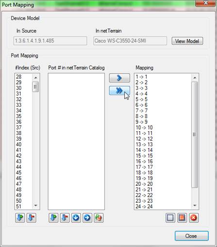
Port mapping using the double arrow button
To remove a mapping from the list, simply select the desired mapping and hit the ‘Delete selected mapping’ button on the lower right corner of the dialog. The two buttons on the left of the delete button can be used to deselect, or select all mappings, in case you need to operate on the whole set without having to click on each mapping.
Attention!
The counts on the left and right column are most likely not going to match. For example, the SNMP discovery may bring in VLANs, which most likely will not match a netTerrain port (unless these are also modeled for the device type). Don’t worry; during the mapping process the ITK will only map as many ports as the lesser of the two counts.
7.2.12 Viewing ports in netTerrain
Ports in netTerrain are never inserted or deleted, as they are part of the device (or card) definition. As such, the reconciliation process for ports in the ITK is automatic: the user does not have to reconcile ports specifically; it is done in conjunction with the reconciliation of the parent devices if port monitoring is enabled. Also, the reconciliation process for ports only involves updates (again, ports cannot be inserted or deleted). If the port monitoring is disabled, the actual physical ports for each device will still exist in netTerrain! They will just not contain any updated values coming from an SNMP discovery.
As we know, ports only reside in the backplane of an equipment or card. Once reconciled, ports in netTerrain will contain the latest SNMP discovered values as part of their properties, assuming the catalog port object includes the MIB properties.
The screenshot of the device backplane below shows ports with status colors. We are taking advantage of the ifOperStatus MIB values and configured a visual override so that when the status value is up, the port is green, and when it is down, the port is red.
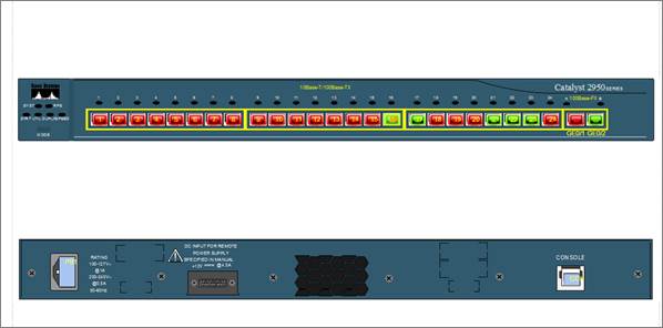
Device backplane view after a device reconciliation with port discovery enabled
In sum: to bring in port information via SNMP, you need the following:
- Port monitoring enabled in Global Settings.
- Port monitoring parameters enabled for the device IP address range.
- Port numbers mapped for the parent device type.
7.2.13 SNMP link discovery
The ITK Native SNMP engine can discover IP address tables and routing tables, which can be used to represent layer 3 links in netTerrain. For every device that has n routes to n destination IP addresses the ITK will create n links.
The ITK can also discover layer 2 links by discovering MAC address tables and bridging tables, which can be used to represent layer 2 links in netTerrain.
For the link discovery to work, we first need to enable our configuration options in the appropriate configuration section (ctrl-g->SNMP). You can have layer 3 enabled and layer 2 disabled or vice versa if you prefer.
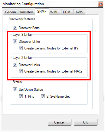
SNMP link discovery configuration
Just like with any other method for automatically bringing in links into netTerrain from an external source, the layer 2 and layer 3 link discovery processes require active link connectors to import data into netTerrain. The good news is that you don’t need to know how to create them since the ITK creates these connectors automatically when you enable the layer 2 or layer 3 link discovery options.
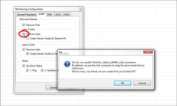
Automatic SNMP layer 3 link connector creation dialog
Click on the ‘OK’ button if you haven’t already created the connector beforehand.
If you choose to have the ITK create the SNMP link connectors for you, the application restarts, the link connectors are registered and displayed in the link connectors view using the default name (‘Native_SNMP_Links’ for layer 3 and ‘Native_SNMP_Links_Layer2’ for layer 2).
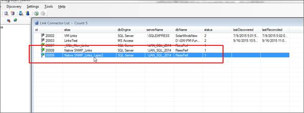
ITK generated SNMP link connector
7.2.13.1 Discovering Layer 3 link data
From a networking perspective layer 3 links are usually routes between routers and layer 2 links are links between switches. In the SNMP configuration section, when the ‘Layer 3 links’ option is checked, the ‘Create generic nodes for external IPs’ will also be enabled. If you check this option for the first time, then the ITK will show you the following message:
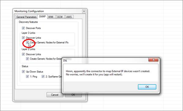
Enabling the Native SNMP_External_IPs connector
What’s happening here? Very simple, external IPs are reconciled in netTerrain using a bread and butter node connector, but instead of you having to figure out how to create it, the ITK can do it automatically. A new connector called ‘Native SNMP_External_IPs’ is created and mapped to the node type ‘Node’ in netTerrain.
Later, when you discover layer 3 links, netTerrain will also automatically create generic nodes for any IP addresses that exist in the routing tables, which are not part of the registered IP address (i.e. not directly discoverable via SNMP).
7.2.13.2 Running the layer 3 link discovery and reconciliation
With the layer 3 link discovery enabled and the layer 3 link connector created we can now discover and reconcile these links in netTerrain. The link discovery is triggered automatically as soon as you start the SNMP discovery, so there are no extra steps involved, but if during the configuration process you checked the ‘Create Generic Nodes for External IPs’ option, then you must also discover these external IP addresses by doing a discovery of the ‘Native SNMP_External_IPs’ connector.
Reconciling the links in netTerrain requires three connectors to be reconciled:
- The SNMP connector.
- The ‘Native SNMP_External_IPs’ (if you want to display external IP address).
- The Native_SNMP_Links connector.
Sounds too complicated? It’s not remember you can simply enable all these connectors and run the scheduler and forget about all these details.
After the reconciliation process is complete you can now view the devices, nodes and links created in netTerrain, such as the example below.
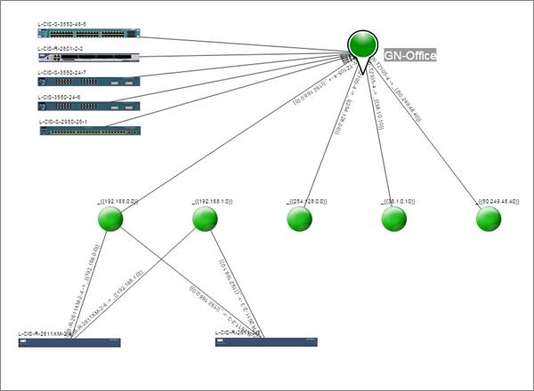
Snapshot of Graphical Networks__’ very own lab discovered with netTerrain
7.2.13.3 Discovering Layer 2 link data
The process for discovering layer 3 link data is very similar to the steps involved for layer 3 links.
Just as with layer 3, in the SNMP configuration section, you may be prompted with a message to automatically create the layer 2 link connector upon checking it from the settings.
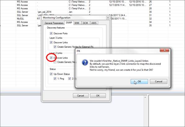
Enabling the layer 2 link connector
When the ‘Layer 2 links’ option is checked, the ‘Create generic nodes for external MACs’ will also be enabled. If you check this option for the first time, then the ITK will show you the following message:
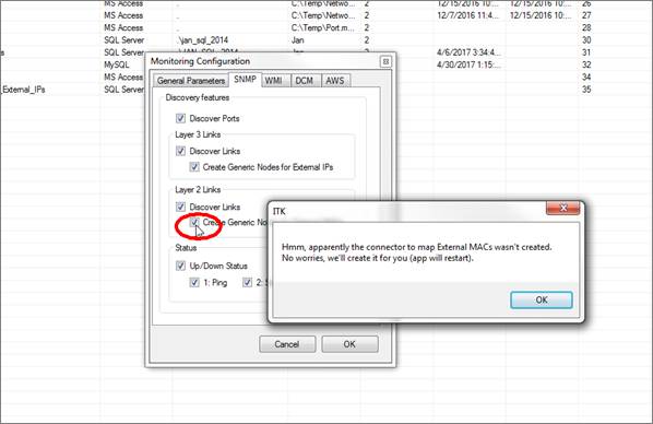
Enabling the Native SNMP_External_MACs connector
Again, as with layer 3, a new connector called ‘Native SNMP_External_MACs’ is created and mapped to the node type ‘Node’ in netTerrain.
Later, when you discover layer 2 links, netTerrain will also automatically create generic nodes for any MAC addresses that exist in the bridging tables of your discovered switches, which are not part of any discovered MAC address tables.
7.2.13.4 Running the layer 2 link discovery and reconciliation
With the layer 2 link discovery enabled and the layer 2 link connector created we can now discover and reconcile these links in netTerrain. The link discovery is triggered automatically as soon as you start the SNMP discovery, so there are no extra steps involved, but if during the configuration process you checked the ‘Create Generic Nodes for External MACs’ option, then you must also discover these external MAC addresses by doing a discovery of the ‘Native SNMP_External_MACs’ connector.
Reconciling the links in netTerrain requires three connectors to be reconciled:
- The SNMP connector.
- The ‘Native SNMP_External_MACs’ (if you want to display external MAC addresses).
- The Native_SNMP_Links_Layer2 connector.
Below is a diagram of a layer 2 and layer 3 topology, showing layer 3 links in green and layer 2 links in blue.
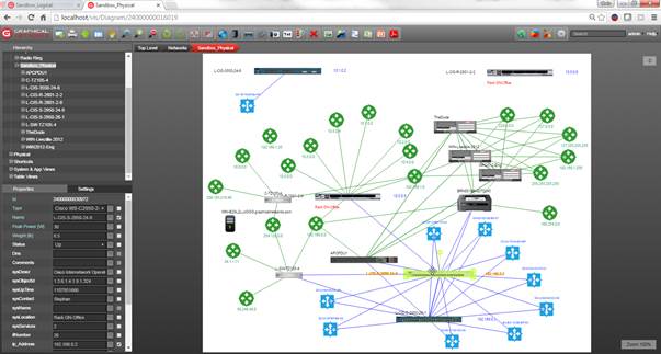
Snapshot of Graphical Networks__’ very own lab with layer 2 and layer 3 links
7.2.14 Using custom MIBs
In addition to the standard MIB OIDs that are embedded in the ITK, users can also use any other MIB OIDs to be discovered via SNMP.
Custom MIBs can be assigned to any particular IP address or range of IP addresses. This is especially useful when you want to discover specific properties for certain device types, such as MIBs that are part of the private enterprise branch.
When you create a new MIB OID field for an IP address, you are in essence instructing the SNMP engine to issue a get request for that particular MIB OID and that particular IP address range. This custom MIB must be mapped to a specific field in netTerrain, so that upon a reconciliation, the engine can populate that field in netTerrain with the discovered values for that MIB.
To add a new custom MIB OID, follow these steps:
- Open the IP address manager (Ctrl-I).
- Choose the IP address for which you want to apply the custom MIBs.
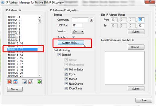
- Click on the Custom MIBS button (as shown above).
- In the custom MIBs dialog type the MIB OID string and map it to the field in netTerrain, such as the example below, where we are creating a new MIB OID that maps external temperature values for a sensor with a field in netTerrain called ‘Ext. Temperature’.
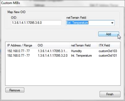
- You can remove custom fields, by highlighting them and clicking on the ‘Remove’ button.
- Once you are done, click on the Finish button.
Upon a discovery and reconciliation, the SNMP engine will try to discover the values of custom MIB OIDs for any IP addresses that have said MIBs associated.
The example screenshot below, shows our sensor with three custom MIB OID fields mapped to the corresponding netTerrain fields.
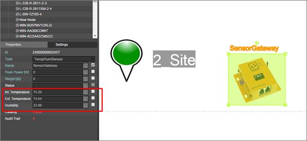
Example of custom MIB OID values mapped to netTerrain
7.3 WMI Discovery
According to Microsoft’s MSDN page, ‘Windows Management Instrumentation (WMI) is the infrastructure for management data and operations on Windows-based operating systems.
Also ‘WMI is the Microsoft implementation of Web-Based Enterprise Management (WBEM), which is an industry initiative to develop a standard technology for accessing management information in an enterprise environment. WMI uses the Common Information Model (CIM) industry standard to represent systems, applications, networks, devices, and other managed components. CIM is developed and maintained by the Distributed Management Task Force (DMTF)’.
The ITK comes equipped with a WMI monitoring tool that discovers WMI instance data for any computers and servers that have the protocol enabled.
Via the WMI protocol, the ITK can discover the following computer related information:
-
Computer System data
-
Operating System
-
CPU characteristics
-
Memory characteristics
-
Logical drives
-
BIOS characteristics
-
Running processes
-
System enclosure data
-
List of installed applications
-
List of web sites configured in IIS (when applicable)
-
List of network adapter configuration parameters
The WMI connector discovers registered computers, their parameters and associated lists, which can then be reconciled in netTerrain.
This module behaves much like a node connector in the sense that it maps the discovered elements with nodes in netTerrain. Moreover, the ITK also has a WMI connector initializer that uses a pre-defined node connector specifically for WMI. This predefined connector is part of the node connector list and is called ‘_WMI_Hosts’. This connector can also be scheduled for automatic discovery and reconciliation, just like any other connector.
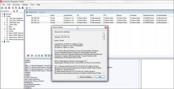
WMI discovery list view
The WMI discovery configuration can be accessed from the Settings->Monitoring-> WMI menu.
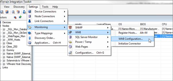
WMI configuration menus and settings
7.3.1 Initializing the WMI connector
As mentioned above, netTerrain utilizes a standard connector to reconcile WMI information from the ITK to netTerrain. This connector is called ‘_WMI_Hosts’ and generated automatically upon initialization.
This connector is also mapped to a node type in netTerrain of the same name, which has predefined fields and an icon automatically created for you upon WMI initialization.
By default, the WMI monitoring function is not enabled and the connector and netTerrain type do not exist. You could create everything yourself, but then you would need to know a thing or two about where the source data resides, what fields to pull and how to map them. Thankfully there is a simple process to automatically create the connector, the netTerrain type and enable the monitoring in one click. Simply go to Settings-> Monitoring->WMI->Initialize connector.
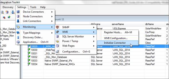
Initializing the WMI monitor
7.3.2 Registering WMI hosts
WMI hosts will not just happily hand over the data to the ITK. You need to register the instances in the ITK first, providing valid credentials that can read the WMI data.
To register a WMI instance go to Settings-> Monitoring->WMI->Register Hosts... and fill out the proper credentials in the dialog that pops up.
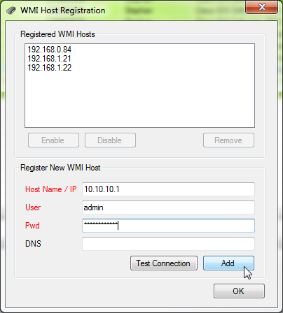
WMI host registration process
If the proper credentials have been passed the host instance should be reachable. You can test this by clicking on the ‘Test connection’ button.
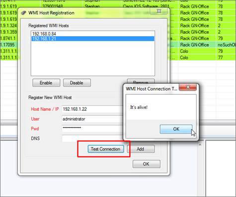
Reachable host
After testing the WMI connectivity, register the host by clicking on ‘Add’. You can edit the credentials for an existing host as well, by clicking on it, editing the values and then clicking on the ‘Update’ button.
To remove a host from the list, simply click on it and press ‘remove’.
You can enable or disable individual hosts for discovery by clicking on the host and pressing the ‘enable’ / ‘disable’ button.
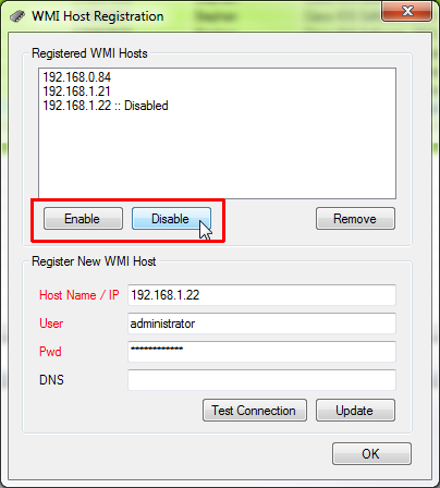
Enabling and disabling hosts for discovery
You can select multiple hosts at once for enabling or disabling.
7.3.3 Setting WMI discovery parameters
The WMI discovery engine has a series of parameters (or templates) and each parameter can collect several data points. You can control which parameters are enabled during the WMI discovery process. To do that, open the monitoring configuration dialog and click on the WMI tab or go to
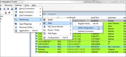
Changing WMI configuration data
In the configuration dialog you can check or uncheck the different templates based on your needs. The only mandatory parameter that the connector always collects is the computer system data.
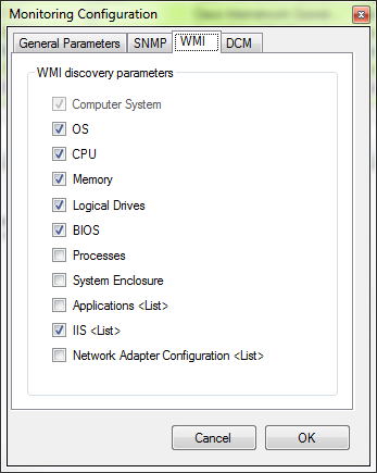
WMI parameters
The following data is collected for WMI host instances:
1) Computer system data:
-
a. Manufacturer
-
b. Roles
2) Operating system:
-
a. Name
-
b. Version
-
c. Caption
-
d. Build number
-
e. Manufacturer
-
f. Code set
-
g. Country code
-
h. Current time zone
-
i. Serial number
3) CPU characteristics (processor):
-
a. Name
-
b. Family
-
c. Manufacturer
-
d. Architecture
-
e. Caption
-
f. Device ID
4) Memory characteristics (physical memory):
-
a. Name
-
b. Manufacturer
-
c. Capacity
-
d. Speed
-
e. Version
-
f. Caption
-
g. Install date
5) Logical drives (logical disk):
-
a. Name
-
b. Caption
-
c. Size
6) BIOS characteristics:
-
a. Manufacturer
-
b. Serial number
7) Running processes:
- a. Name
8) System enclosure data:
-
a. SMBIOS asset tag
-
b. Manufacturer
-
c. Model
-
d. Name
-
e. Part Number
-
f. Serial number
9) List of installed applications:
-
a. Name
-
b. Description
-
c. Install date
-
d. Install location
-
e. Identifying number
-
f. SKU number
-
g. Vendor
-
h. Version
10) List of web sites configured in IIS (when applicable):
-
a. Path
-
b. Site name
-
c. Application pool
-
d. Enabled protocols
11) List of network adapter configuration parameters:
-
a. Caption
-
b. Default IP gateway
-
c. DHCP server
-
d. DNS domain
-
e. DNS host name
-
f. IP address
-
g. MAC address
Templates 9, 10 and 11 actually generate separate tables that can be accessed from the ITK interface, as discussed below.
7.3.4 Discovering WMI host data
To discover WMI host data, simply run a discovery and reconciliation process for the WMI connector, just like you would with any other connector (see chapter 4).
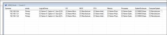
Discovered WMI hosts
WMI hosts, as mentioned before, can show the applications that are installed, network configuration data as well as configured IIS websites (when applicable).
To view this information in the ITK, right click on the host and select the appropriate parameter:
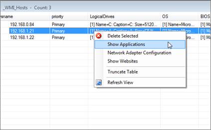
Application, network and website data
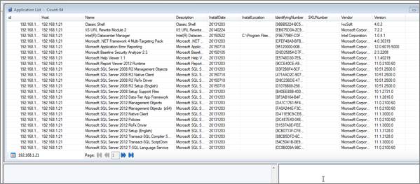
Application list
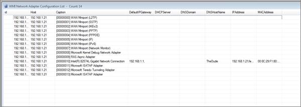
Network adapter list
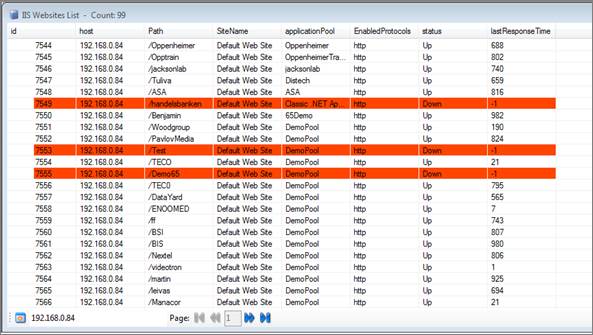
Website list
7.3.5 Setting up and troubleshooting WMI in your environment
The setup process for WMI discovery does come with its kinks: hosts need to have the WMI service enabled, proper permissions need to need to be set up and more. As such, WMI issues may occur during configuration.
RPC errors may occur, which usually mean your settings are not correct and you cannot even get to the server for authentication. This can be a firewall issue or simply a bad DNS or IP address information. Authentication errors usually mean it’s your user and/or password that are incorrect. It may also mean you need to add a different user to the WMI namespace.
7.3.5.1 Adding a user to the WMI namespace
Typically, the default administrator account will work for WMI monitoring. However, if you are using a different administrator account or you want to add an AD user account to use when monitoring WMI then you need to add the user and apply the appropriate permissions for this user account. For troubleshooting purposes, you can use a WMI management tool (WmiMgmt).
To modify the permissions, do the following:
1) Start the WmiMgmt tool
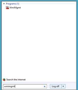
2) Right click the WMI control and select properties
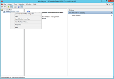
3) Select the appropriate namespace -
a. The default name space is CIMV2
b. If you want to monitor IIS then you would look for the WebAdminstration namespace and apply the security settings to this namespace a well
c. After selecting the namespace press the Security button
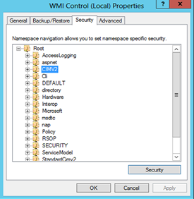
4) Add the user and select the remote enable permissions for the user
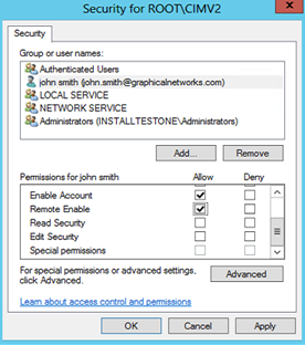
7.3.5.2 DCOM permissions
As part of the WMI set up process on the monitored host, you may also need to add the user to the DCOM settings for the machine. To add the user, you need to go into the properties for the computer following these steps:
1) To get to the DCOM settings start the MMC application
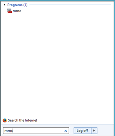
2) Press the Add/Remove snap in option
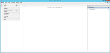
3) Add the snap in called component services, then right click the My Computer icon
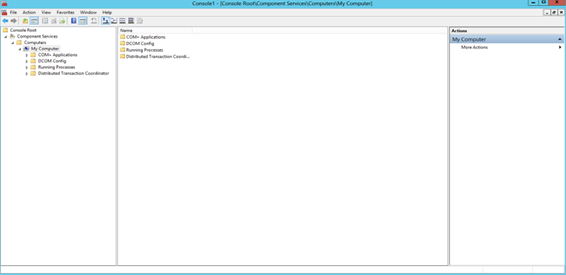
4) Press the COM Security settings and then press the “Edit Limits” for the Launch and Activation Permissions
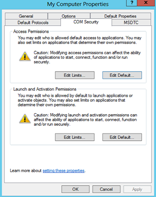
5) Add the user and select the Remote Launch and Remote Activation permissions
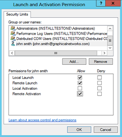
7.3.5.3 Testing a WMI connection
If you are having problems using WMI you may test connectivity issues by using the WBEMTest.exe tool. This is built into most Windows machines and can be used as follows:
1) Start the WBEMtest application by simply typing WBEMTest into your local search engine
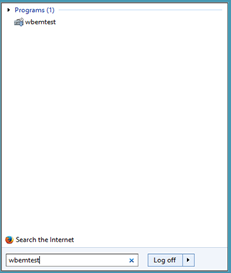
2) Press the connection button
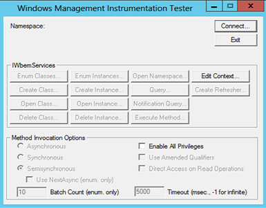
3) Enter the credentials
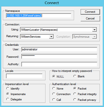
4) If you have a successful connection the services will be active and can be selected
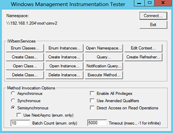
7.4 AWS Discovery
The ITK comes equipped with an AWS monitoring tool that discovers a number of objects related to your AWS environment.
Using the AWS API, the ITK can discover the following AWS related entities:
-
Instances
-
Security groups
-
Security group rules
-
Buckets
-
Health checks
-
Volumes
-
Volume attachments
Just like other utilities (like the WMI, SNMP or SQL), this module behaves much like a node connector in the sense that it maps the discovered elements with nodes in netTerrain. Moreover, the ITK also has an AWS connector initializer that uses a pre-defined node connector specifically for AWS. This predefined connector is part of the node connector list and is called ‘_AWS_instances’. This connector can also be scheduled for automatic discovery and reconciliation, just like any other connector.
This predefined connector will only reconcile AWS instances in netTerrain using a predefined AWS instances type in the catalog. For the other objects that the AWS utility discovers (buckets, health checks, etc.) you would have to create a connector for them manually. To do that, please check the tables that start with adaAws in your GNCORE database. These include:
-
adaAwsBuckets
-
adaAwsHealthChecks
-
adaAwsSecurityGroups
-
adaAwsSecurityGroupsRules
-
adaAwsVolumeAttachments
-
adaAwsVolumes
7.4.1 Initializing the AWS connector
As mentioned above, netTerrain utilizes a standard connector to reconcile AWS instance information from the ITK to netTerrain. This connector is called ‘_AWS_Instances’ and generated automatically upon initialization.
This connector is also mapped to a node type in netTerrain of the same name, which has predefined fields and an icon automatically created for you upon AWS initialization.
By default, the AWS monitoring function is not enabled and the connector and netTerrain type do not exist. You could create everything yourself, but then you would need to know a thing or two about where the source data resides, what fields to pull and how to map them. Thankfully there is a simple process to automatically create the connector, the netTerrain type and enable the monitoring in one click. Simply go to Settings-> Monitoring->AWS->Initialize connector.
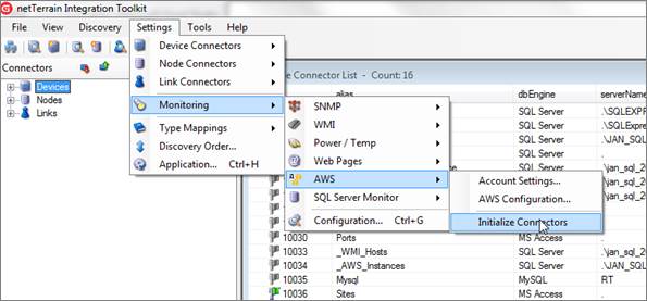
Initializing the AWS monitor
7.4.2 Configuring AWS for first time use
To configure the AWS connector, you need to provide the ITK your AWS account settings and set up some configuration parameters.
7.4.2.1 Storing the AWS account settings
AWS will not just happily hand over the data to the ITK. You need to first provide the AWS account settings in order for the ITK to access the data through the AWS API.
The read AWS data through its API, the ITK needs the AWS Access Key Id as well as the secret key. This is an AWS requirement. The secret key is never shown in clear text and is also encrypted in the backend.
To set up the AWS account go to Settings-> Monitoring->AWS->Register Hosts... and fill out the proper credentials in the dialog that pops up.
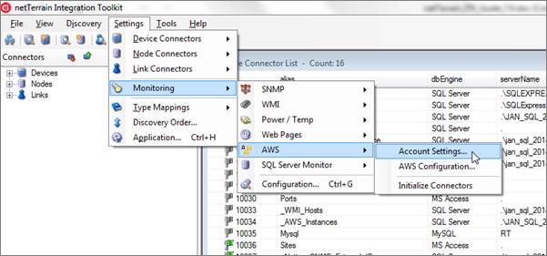
AWS account setup
After the proper credentials have been passed you can proceed to configure the parameters you want discovered from AWS.
7.4.2.2 Configuring AWS parameters
The AWS discovery process discovers the parameters that you enable from the AWS configuration settings section.
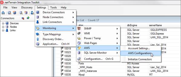
AWS configuration
First make sure AWS discovery is enabled.
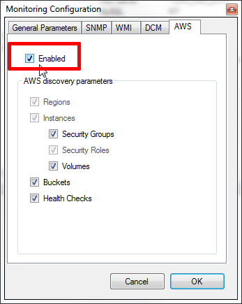
Enabling AWS discovery
You can then choose several parameters to discover and monitor. Notice how Regions, Instances and Security Roles are always discovered
To find out if AWS has been properly set up, you basically need to run a discovery process. This will soon reveal if there were any problems during the set-up process.
7.4.3 Discovering from AWS
To run a discovery, you can simply click on the discovery button on the AWS list or find the newly registered AWS connector located in Discovery->Manual Node Discovery->_AWS_Instances. This discovery process will discover any parameters enabled during the setup but will only display a view of the instances. The rest is available in tables as described above.
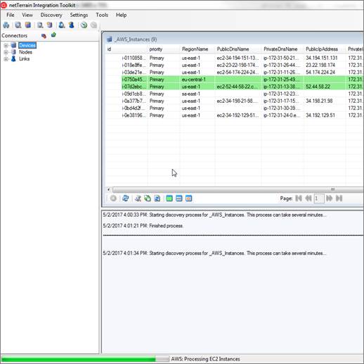
Discovering AWS data
7.5 SQL Server Monitoring
The ITK comes equipped with a simple SQL Server monitoring tool that discovers SQL Server instance data and all the underlying databases along with some of their key parameters.
7.5.1 Initializing the SQL monitoring connector
netTerrain utilizes three standard connectors to pass SQL information from the ITK to netTerrain:
- _SQL_Mon_DbServerInstance node connector: stores information about the SQL Server instances.
- _SQL_Mon_Database node connector: stores information about each SQL Server database on registered instances.
- _SQL_Mon_Links: enables visual links in netTerrain to show which database is associated with which SQL Server.
Each of these three connectors should be mapped to the corresponding type in netTerrain. The netTerrain catalog will require similar types with the appropriate fields for you to take advantage of this monitoring functionality.
By default, the SQL monitoring function is not enabled, and these connectors and types are not created in netTerrain. You could create everything yourself, but then you would need to know a thing or two about where the source data resides, what fields to pull and how to map them. Thankfully there is a simple process to automatically create the connectors and enable the monitoring. Simply go to Settings-> Monitor->SQL Server Monitor->Initialize to create all three connectors in one click.
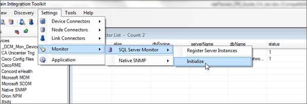
Initializing the SQL Server monitor
This process not only creates the connectors, but also creates the necessary types in netTerrain. Note that if any of the three connector names already exist in the ITK or in the netTerrain catalog, the process will fail with the following message:
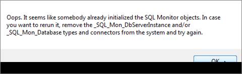
7.5.2 Registering SQL Servers
SQL Server databases will not just happily hand over the data to the ITK. You need to register the instances in the ITK first, providing valid credentials that can read the master databases (many a DBA would cringe at the mere reading of this paragraph, but since the ITK will read statistics for each database from the master database, a user with permissions to read from there must be created in the SQL Server instance).
To register a SQL Server instance, go to Settings-> Monitoring->SQL Server Monitor->Register Server Instances and fill out the proper credentials in the dialog that pops up.
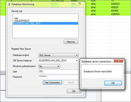
SQL Server registration process
If the proper credentials have been passed (i.e. the server is reachable), the SQL Server instance can be registered. Note that this will not guarantee proper reading of the data, as permissions may not be enough to access the master database.
You can register as many instances as needed, and once this process is completed you can click on the ‘Enable Monitor’ button on the bottom left corner of the dialog and then ‘OK’.
7.5.3 Discovering SQL Server data
To now discover SQL Server data, simply run a discovery and reconciliation process for all three SQL monitoring connectors.
The following data is collected for SQL Server instances:
- Database edition
- Database engine
- Database product level
- Database product version
- Database server instance
- Database server version
- Is trusted flag
- Memory buffer pool committed [Mb]
- Memory buffer pool used [Mb]
- Memory needed workload [Mb]
- Memory OS physical [Mb]
- Memory OS virtual [Mb]
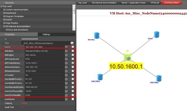
SQL Server database view
Databases for each instance will be discovered automatically and linked to the parent instance, as the image above shows. The following data is collected for SQL Server databases:
- Create date
- Database_id
- Database name
- Data file name
- Data file size
- Database engine
- Database server instance
- Log file name
- Log file size
8 Other settings and commands
8.1 Commands
The ITK can issue commands from the input window (bottom right window of the switchboard).
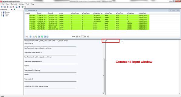
Command input window
These commands can trigger events that affect data in the ITK or in netTerrain.
The command input window is mainly used for development and consulting purposes, but the following commands have been made available for end users:
addFieldToAllCards\<fieldName>- adds given field to all card types in catalogaddFieldToAllDevices\<fieldName>- adds given field to all device types in catalogaddFieldToAllLinkTypes\<fieldName>- adds given field to all link types in catalogaddFieldToAllNodeTypes\<fieldName>- adds given field to all node types in catalogaddporttomodel\<decimal typeid>?<string portname>- adds a port to the model (and all instances) of the given type using the given nameaddFieldToAllRacks\<fieldName>- adds given field to all rack types in catalogaddSnmpPortFields- adds all missing port properties that are discovered via snmp to port object in netTerrainsetDefaultForAllCardTypes\<fieldName>?<defaultValue>- sets a default value to a given field for all card types in catalogsetDefaultForAllDeviceTypes\<fieldName>?<defaultValue>- sets a default value to a given field for all device types in catalog
setDefaultForAllLinkTypes\<fieldName>?<defaultValue>- sets a default value to a given field for all link types in catalogsetDefaultForAllNodeTypes\<fieldName>?<defaultValue>- sets a default value to a given field for all node types in catalogsetDefaultForAllRackTypes\<fieldName>?<defaultValue>- sets a default value to a given field for all rack types in catalogapplyDefaultToCardInstancesOfType\<string typeName>?<fieldName>- applies the default value of a given field to all instances of that specific card typeapplyDefaultToDeviceInstancesOfType\<string typeName>?<fieldName>- applies the default value of a given field to all instances of that specific device typeapplyDefaultToLinkInstancesOfType\<string typeName>?<fieldName>- applies the default value of a given field to all instances of that specific link typeapplyDefaultToNodeInstancesOfType\<string typeName>?<fieldName>- applies the default value of a given field to all instances of that specific node typeapplyDefaultToRackInstancesOfType\<string typeName>?<fieldName>- applies the default value of a given field to all instances of that specific rack typeapplyDefaultToCardInstancesAllTypes\<fieldName>- applies the default value of a given field to all instances of all card typesapplyDefaultToDeviceInstancesAllTypes\<fieldName>- applies the default value of a given field to all instances of all device typesapplyDefaultToLinkInstancesAllTypes\<fieldName>- applies the default value of a given field to all instances of all link typesapplyDefaultToNodeInstancesAllTypes\<fieldName>- applies the default value of a given field to all instances of all node typesapplyDefaultToRackInstancesAllTypes\<fieldName>- applies the default value of a given field to all instances of all rack types<ARROW DOWN>- displays last command in buffer<ARROW UP>- displays first command in bufferclearSnmpAddressTable- deletes contents from the SNMP IP address tableclearSnmpRouteTable- deletes contents from the SNMP routing tablecls- clears output screendeleteDefaultFromAllCardTypes\<fieldName>?<defaultValue>- sets the default value to given field for all card types in catalog to NULLdeleteDefaultFromAllDeviceTypes\<fieldName>?<defaultValue>- sets the default value to given field for all device types in catalog to NULLdeleteDefaultFromAllLinkTypes\<fieldName>?<defaultValue>- sets the default value to given field for all link types in catalog to NULLdeleteDefaultFromAllNodeTypes\<fieldName>?<defaultValue>- sets the default value to given field for all node types in catalog to NULLdeleteDefaultFromAllRackTypes\<fieldName>?<defaultValue>- sets the default value to given field for all rack types in catalog to NULLdeleteFieldForAllCards\<fieldName>deleteFieldForAllDevices\<fieldName>deleteFieldForAllLinkTypes\<fieldName>deleteFieldForAllNodeTypes\<fieldName>deleteFieldForAllRacks\<fieldName>deleteUnusedNonSystemLinksdeleteUnusedNonSystemNodesdisabledc- disables all device connectorsdisablelc- disables all link connectorsdisablenc- disables all node connectorsenabledc- enables all device connectorsenablelc- enables all link connectorsenablenc- enables all node connectors<ESC>- clears input<F5>- clears buffermibget\ip:<ip address>oid:<mib oid>comm:<community string>- gets MIB value for given IP address and OID.oid\<oid>- finds matching model to oidping\<ip address>- pings the given ip address or namepl- purges logportmonoff- disables SNMP port monitoring for all ip addressesportmonon- enables SNMP port monitoring for all ip addressesresequenceConnectors- reindexes all connector sequencess0- disables silent modes1- runs discovery in silent mode (no output of individual records)walk\ip:<ip address>oid:<mib oid>- walks a MIB stubtree for a given IP address and root OID. Example: walk\ip:192.168.1.1oid:1.3.6.1.2unfavoriteAllCategoriesunfavoriteAllDeviceTypes
8.2 Other application settings
From the Settings->Application menu you can open the application settings dialog to configure certain global parameters in the ITK.
Besides the scheduler settings (explained above), from here we can also set the following parameters:
- records per page on list views
- app server URL (to access netTerrain directly from the ITK)
- silent mode
- size of the output buffer
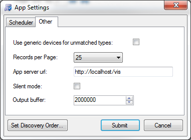
Other application settings